LPC812 MAX Experiment: Overview
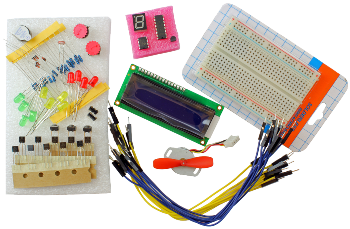
The LPC812 MAX Experiment Kit has been created as a guided tour to learn embedded programming with the mbed framework and the NXP’s LPC800 microcontroller family with Cortex-M0+ core. The experiments are performed on a breadboard for maximum flexibility and ease of use.
The component kit can be bought from Embedded Artists. In order to perform the experiments an LPC812 MAX board is also required. This board must be bought separately.
All experiments are based on the LPC812 MAX board, but the experiments can easily be ported to other mbed platforms.
This page is the starting page for all documentation about the experiments.
Getting Started
As a first step it is recommended to read the Getting Started Tour. It contains information about how to work with the on-line compiler and how to download and execute the code.
Experiments
It is recommended to follow the order of the experiments. They have been compiled to give you the best learning curve. There are often multiple small steps in each experiments and they build upon each other. Where appropriate, shorter theoretical discussions have been added.
These are the experiments:
- Digital Outputs
- Digital Inputs
- Control Multiple LEDs
- Work with a Serial Bus - UART
- Analog Input
- Pulse Width Modulation
- 7-Segment Display
- Work with a Serial Bus - SPI
- Interrupts
- Work with a Serial Bus - I2C
- Expansion Port - XBee and GPS
- Character LCD
- Stepping Motor
Component Kit
In this section we will take a closer look at the different components included in the kit.
Note that all components are not used in the experiments, for example the diodes, the NPN transistors and the temperature sensor. These components are left as an exercise to use in own experiments.
The table below contains photos and a description of all components in order to simplify identification. Note that photos are only typical in the sense that they illustrate the components typical visual appearance. Exact appearance can differ for the components in the kit that you have received. The number of components shown in a picture can also differ from delivered quantity.
Most components are specified with a Digikey or Mouser equivalent. If a component gets damaged, a new one can typically be ordered from Digikey, Mouser or any preferred component distributor. The Digikey/Mouser number is just to get the key data of the component. The actual components in the component kit might very well be of different brands.
| Component | Description | Note |
|---|---|---|
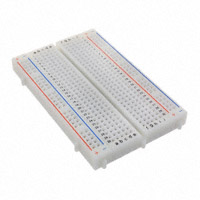 | Breadboard http://en.wikipedia.org/wiki/Breadboard | Digikey: 438-1109-ND Mouser: 854-BB400T |
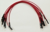 | Cables, male-to-male http://en.wikipedia.org/wiki/Jump_wire | Prototype cables can be ordered from Embedded Artists web shop in 50 pcs packages (EA-ACC-017). |
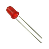 | LEDs 4 Red 4 Green 4 Yellow http://en.wikipedia.org/wiki/Led | This component is polarized. One of the two pins is longer than the other. This is the positive side, the anode. There is also a small cut on the side of the plastic package. This is on the short pin side, which is the negative side, the cathode. Any 5mm LED with Vf around 1.7V (for red LED) and 150mcd at 20mA current will work, for example: Red LED; Digikey: 1080-1136-ND Green LED: Digikey: 1080-1059-ND Yellow LED; Digikey: 1080-1094-ND |
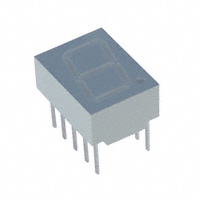 | 7-segment LED http://en.wikipedia.org/wiki/7-segment_display | This component is polarized. Pin 1 is in the lower left corner in the picture to the left. |
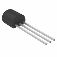 | NPN transistor, BC547B http://en.wikipedia.org/wiki/Bjt_transistor | This component is polarized. One side of the plastic package is flat and the other side is rounded. When mounting this component make sure it is turned correctly. ON Semiconductor: BC547BRL1G Digikey: BC547BZL1GOSCT-ND Mouser: 863-BC547BRL1G This component is currently not used in any experiment but can for example be used to drive higher current through a LED |
 | PNP transistor, BC557B http://en.wikipedia.org/wiki/Bjt_transistor | This component is polarized. One side of the plastic package is flat and the other side is rounded. When mounting this component make sure it is turned correctly. ON Semiconductor: BC557BRL1G Digikey: BC557BRL1GOSCT-ND Mouser: 863-BC557BRL1G |
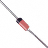 | Diode, 1N4148 http://en.wikipedia.org/wiki/Semiconductor_diode | This component is polarized. One side of the plastic package is flat and the other side is rounded. When mounting this component make sure it is turned correctly. Diodes Inc.: 1N4148-T Digikey: 1N4148DICT-ND Mouser: 621-1N4148-T This component is currently not used in any experiment. |
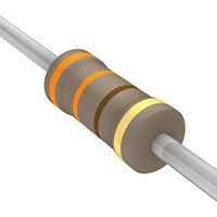 | Resistor, 330 ohm | Color: Orange, Orange, Black, Black This is not a polarized component. Yageo: CFR-25JB-52-330R Digikey: 330QBK-ND |
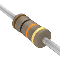 | Resistor, 10Kohm | Color: Brown, Black, Orange, Black This is not a polarized component. Yageo: CFR-25JB-52-10K Digikey: 10KQBK-ND |
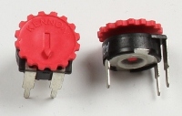 | Trimming potentiometer, 22 Kohm http://en.wikipedia.org/wiki/Potentiometer | 10Kohm equivalent from Bourns Inc.: 3352E-1-103LF Digikey: 3352E-103LF-ND |
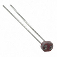 | Photo resistor http://en.wikipedia.org/wiki/Photo_resistor | This is not a polarized component. Advanced Photonix: PDV-P9002-1 Digikey: PDV-P9002-1-ND |
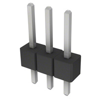 | Pin list, 1x3 | Sullins: PEC03SAAN Digikey: S1012E-03-ND This component is currently not used in any experiment but can for example be used to connect to a servo motor (that typically has a 3 pos connector). |
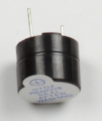 | Piezo buzzer http://en.wikipedia.org/wiki/Buzzer | This component is polarized. One pin is longer than the other. The longer pin is the positive side. The top label also indicates this side with a small plus sign. CUI Inc.: CEP-2242 Digikey: 102-1115-ND |
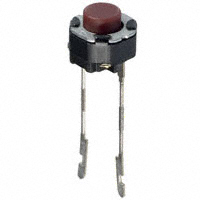 | Pushbuttons for breadboard | These switches are for breadboard usage. Note that the pins must be cut to suitable length before mounted in the breadboard. Panasonic: EVQ-11L05R Digikey: P8079SCT-ND Mouser: 667-EVQ-11L05R |
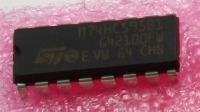 | Shift register, 74HC595 http://en.wikipedia.org/wiki/Shift_register | This component is polarized. There is a cut in one end of the plastic package, on the short side. This indicates where pin 1 is located – lower left side in the picture to the left. When mounting this component make sure it is turned correctly. NXP: 74HC595N Digikey: 568-1484-5-ND Mouser: 771-74HC595N |
 | Temperature sensor, MCP9701 | This component is polarized. One side of the plastic package is flat and the other side is rounded. When mounting this component make sure it is turned correctly. Microchip: MCP9701-E/TO Digikey: MCP9701-E/TO-ND Mouser: 579-MCP9701-E/TO This component is currently not used in any experiment. |
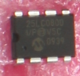 | SPI flash, 25LC080 http://en.wikipedia.org/wiki/Flash_memory | This component is polarized. There is a cut in one end of the plastic package, on the short side. This indicates where pin 1 is located. When mounting this component, make sure it is turned correctly. Microchip: 25LC080D-I/P Digikey: 25LC080D-I/P-ND Mouser: 579-25LC080D-I/P |
 | L293D, Step motor driver | Texas Instruments: L293DNE Digikey: 296-9518-5-ND Mouser: 595-L293DNE |
 | Step motor, bipolar http://en.wikipedia.org/wiki/Stepper_motor | Model: 20BY20L033 with 86 ohm winding resistance. Custom designed step motor designed for low-torque, 3.3V applications. Datasheet: 20BY20L033.pdf |
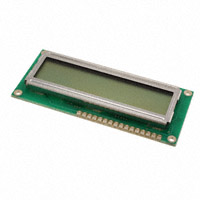 | 2x16 character LCD with blue backlight | Topway: LMB162AFC-2 datasheet: http://www.topwaydisplay.com/Pub/Manual/LMB162AFC-2-Manual-Rev0.1.pdf |
Please log in to post comments.
