LPC812 MAX Experiment: Analog Input
Experiment: Analog Input
In this experiment you will learn how to convert an analog signal to a digital value. There is no ADC (Analog to Digital Converter) on the LPC812 microcontroller, however the LPC812 MAX board has a PCF8591 chip which have four analog inputs and is accessed with I2C.
Software
The I2C bus is explained in the I2C Experiment so for now a helper class is supplied to help you get started with the analog inputs without prior knowledge of how I2C works. The class is PCF8591:
Use the "Import Library" button to copy it into your project.
1) Hardware
In this lab you will need:
- 1x breadboard
- 1x trimming potentiometer
- 1x 330 ohm resistor
- cables
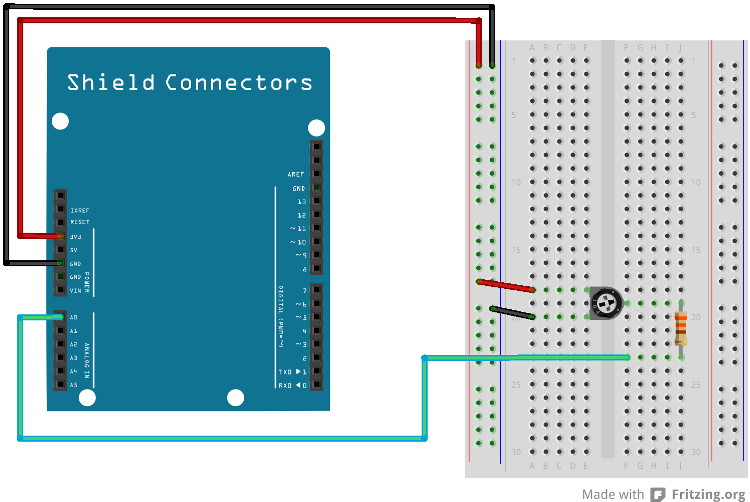
Mount the components on the breadboard and connect the breadboard to the LPC812 as show in the image below.

The pin(s) are specified in the mbed library with the actual pin names as well as some useful aliases:
| Schematic Name | mbed Pin Name | Arduino Shield Alias | Description |
|---|---|---|---|
| AIN0_XPIO0 (SJ5 in 1-2 pos) | N/A | A0 | Analog In |
| PIO0_10 | P0_10 | A4 (but it is not an analog input) | I2C SDA |
| PIO0_11 | P0_11 | A5 (but it is not an analog input) | I2C SCL |
1) Description
In this experiment we shall read the value of analog input #0. You will be using a trimming potentiometer mounted on the breadboard as shown above. The trimming potentiometer is connected to ground and +3.3V in each end. By rotating the trimming potentiometer it is possible to adjust the analog voltage to any value between 0V and +3.3V. This corresponds to the input range of the ADC. When converting the analog value, the ADC has 8-bit resolution - meaning that the result will be in the range of 0-255, or 0x00-0xff in hexadecimal notation. 0V input gives the converted value 0 and +3.3V input gives the converted value 255.
Create a function for reading the analog value of a specified analog channel. Use the following as a starting point:
main.cpp
#include "mbed.h"
#include "PCF8591.h"

Serial pc(USBTX, USBRX); // tx, rx
PCF8591 adc;

float getTrimpotValue()
{
    // read the value
    int v = adc.read(PCF8591::A0);

    // convert it from 0..255 to 0-3.3V
    ....
    return ...;
}

int main() {
    pc.printf("Analog input tests");
    while(1) {
        pc.printf("%f V\n", getTrimpotValue());
        wait(0.25);
    }
}
2) Description
The trimming potentiometer will be used in future labs as a way to control for example the 7-segment display. Modify your program so that turning the trimming potentiometer results in integer values from 0 to 9.
main.cpp
#include "mbed.h"
#include "PCF8591.h"

Serial pc(USBTX, USBRX); // tx, rx
PCF8591 adc;

int getDigit()
{
    // read the value
    int v = adc.read(PCF8591::A0);

    // convert it from 0..255 to 0..9
    ....
    return ...;
}

int main() {
    pc.printf("Analog input one digit test");
    while(1) {
        pc.printf("%d\n", getDigit());
        wait(0.25);
    }
}
3) Hardware
In this lab you will need:
- 1x breadboard
- 1x photo resistor
- 1x 330 ohm resistor
- cables
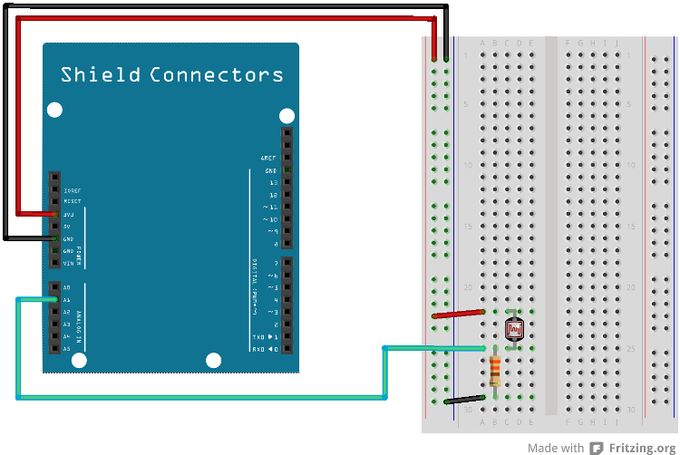
Mount the components on the breadboard and connect the breadboard to the LPC812 as show in the image below.

The pin(s) are specified in the mbed library with the actual pin names as well as some useful aliases:
| Schematic Name | mbed Pin Name | Arduino Shield Alias | Description |
|---|---|---|---|
| AIN1_XPIO1 (SJ6 in 1-2 pos) | N/A | A1 | Analog In |
| PIO0_10 | P0_10 | A4 (but it is not an analog input) | I2C SDA |
| PIO0_11 | P0_11 | A5 (but it is not an analog input) | I2C SCL |
3) Description
In this experiment a light sensor will provide the analog input value (instead of a trimming potentiometer). The more light the sensor is exposed to, the lower the resistance become. Adjust the program code in the first experiment to read from A1 (instead of A0) and check what converted values to expect in different light conditions.
What is the range of values between absolute dark and full sunlight?
You will notice some noise in the converted values. It is not always a stable value. This is quite normal to expect in a not-noise-optimized setup that we have with the breadboard and the LPC812 MAX board. Besides proper hardware design, a method to handle noise is to low-pass filter the converted values. Below are two examples of how this can be done. It is a simple first-order filter. The closer to 1 ALFA is, the more filter effect is applied (the lower the cut-off frequency will be in the filter). One example (where ALFA is 0.875) is outlined below.
//Floating point calculations
#define ALFA 0.875
newValue = ALFA*newValue + (1-ALFA)*newSample;
or
//Integer calculations
newValue = ((7*newValue) + newSample) >> 3
Test to filter the samples and observe that they will be more smooth and stable. Also note that the more you filter the values the longer it will take for the filtered value to change as you affect the sensor.
4) Description
Another way to handle noise (varying values from an analog signal) is to introduce threshold handling. In this exercise you shall implement a program that reports when the value of an analog signal has changed more than a set limit. Create a program that prints the value of A0 in the console whenever the change in value s large than 2% of the full scale.
Tip #1: 2% of 256 steps equals 5.12, which can be rounded down to 5.
Tip #2: Remember the last reported value and compare the new sample against this value. If you compare against the previous samples value then it is theoretically possible to slowly, slowly turn the trimming potentiometer without getting any change report event.
As an extra experiment, create a program that reports changes as above. However, if no changes are detected, report the current value once every 5 seconds.
Solution(s)
Import programlpc812_exp_solution_analog-in
Solutions for the Analog Input experiments for LPC812 MAX
Please log in to post comments.
