LPC812 MAX Experiment: Expansion Port
Experiment: Expansion Port - RF
In this experiment you will learn how to work with radio modules. The first part requires one RF Adapter Board and an XBee module. Embedded Artists sells the RF Adapter board either standalone or in a bundle with an XBee module.
In the second part you will work with a GPS module from Embedded Artists.
Information
If you buy the RF Adapter Board, don't forget to also buy a 14-pos IDC Ribbon Cable 50 mil so that you can connect it to the LPC812 MAX board.
1) Hardware
This exercise requires at least two XBee modules and the same number of experiment boards to be able to test XBee communication. One of the boards will be setup as a controller and the other(s) as node(s).
There are many different XBee modules with different functionality and programming interfaces. The XBee module used in this experiment is: XB24-AWI-001. It can be bought from for example Digikey: XB24-AWI-001-ND or Mouser: 888-XB24-AWI-001.
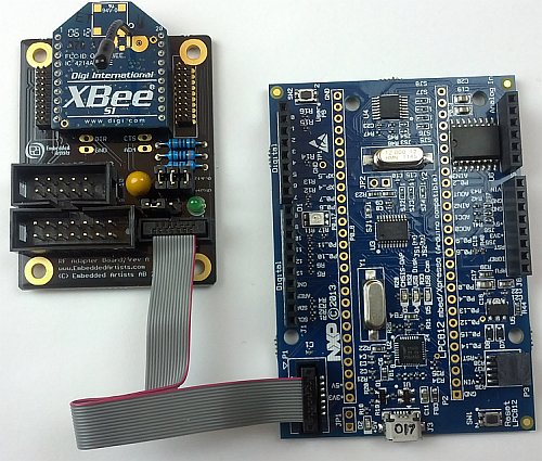
Connect the experiment boards to the RF Adapter Boards with a 14-pos IDC Ribbon Cable 50 mil and then mount the XBee module on the RF Adapter Boards like this:

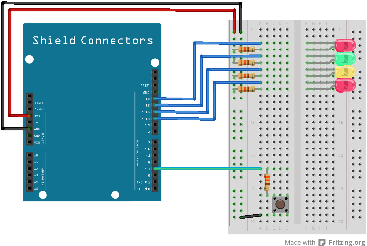
In this lab you will need:
- 1x breadboard
- 1x push-button
- 5x 330 ohm resistor
- 1x yellow LED
- 1x green LED
- 2x red LED
- cables
Mount the components on the breadboard and connect the breadboard to the LPC812 as show in the image below.

The pin(s) are specified in the mbed library with the actual pin names as well as some useful aliases:
| Schematic Name | mbed Pin Name | Arduino Shield Alias | Description |
|---|---|---|---|
| PIO0_0 | P0_0 | D0 | UART RX |
| PIO0_4 | P0_4 | D1 | UART TX |
| PIO0_8 | P0_8 | D3 | Push-button |
| PIO0_17 | P0_17 | D8 | XBee Reset Signal (and RGB Green) |
| PIO0_11 | P0_11 | A5 | XBee Sleep Signal |
| PIO0_13 | P0_13 | D10 | led4 |
| PIO0_14 | P0_14 | D11 | ackLed |
| PIO0_15 | P0_15 | D12 | remoteBtnLed |
| PIO0_12 | P0_12 | D13 | xbeeInitLed |
1) Description
The XBee driver is a part of the EALib for the LPC4088 QuickStart Board:
Import library
Public Types |
|
| enum | XBeeError |
|
Error codes returned from public methods. More... |
|
| enum |
CallbackType
{
CbDeviceUp = 0, CbDeviceDown , CbNodeFound , CbTxStat , CbDataAvailable } |
|
Callback function/method types. More... |
|
| enum | XBeeType |
|
Xbee types. More... |
|
| enum | XBeeTxStatus |
|
Transmit status. More... |
|
Public Member Functions |
|
| XBee (PinName tx, PinName rx, PinName reset, PinName sleep) | |
|
Create an interface to an
XBee
module.
|
|
| XBeeError | init ( XBeeType type, const char *panId) |
|
Initialize the
XBee
module and configure it to be of a specific type.
|
|
| void | registerCallback (void(*fptr)(void), CallbackType type) |
|
Register a callback function.
|
|
| template<typename T > | |
| void | registerCallback (T *tptr, void(T::*mptr)(void), CallbackType type) |
|
Register a callback method.
|
|
| void | process () |
|
Call this method repeatedly to process incoming data.
|
|
| XBeeError | getRemoteAddress (uint32_t *addrHi, uint32_t *addrLo) |
|
Get address of remote node.
|
|
| XBeeError | getRssi (uint8_t *rssi) |
|
Get signal strength indicator value (RSSI).
|
|
| XBeeError | getTxStatus (uint8_t *frameId, XBeeTxStatus *status) |
|
Get the transmit status.
|
|
| XBeeError | getData (char **data, uint8_t *len) |
|
Get received data.
|
|
| XBeeError | send (uint32_t addrHi, uint32_t addrLo, char *data, uint8_t len, uint8_t *frameId) |
|
Send data to a node with specified address.
|
|
| XBeeError | discoverNodes () |
|
Send a Node Discover request.
|
|
| XBeeError | enterSleep () |
|
Request the module to enter sleep mode.
|
|
| XBeeError | exitSleep () |
|
Request the module to exit sleep mode.
|
|
The library cannot be used directly but the XBee class and a main program is available here:
Import programlpc812_exp_solution_exp-port-xbee
Solutions for the XBee experiments for LPC812 MAX
Take a look at the main.cpp file in the program above.
static bool xbeeInit()
{
    xbee.registerCallback(xbeeDeviceUp, XBee::CbDeviceUp);
    xbee.registerCallback(xbeeDeviceDown, XBee::CbDeviceDown);
    xbee.registerCallback(xbeeNodeFound, XBee::CbNodeFound);
    xbee.registerCallback(xbeeTxStat, XBee::CbTxStat);
    xbee.registerCallback(xbeeDataAvailable, XBee::CbDataAvailable);

#ifdef NODE_IS_COORDINATOR
    XBee::XBeeError err = xbee.init(XBee::Coordinator, "EAEA");
#else
    XBee::XBeeError err = xbee.init(XBee::EndDevice, "EAEA");
#endif
    if (err != XBee::Ok) {
        return false;
    }

    return true;
}
The XBee driver is provided five callbacks during initialization. The callbacks will be called when the
driver has completed initialization of the XBee module (xbeeDeviceUp), when a new node is discovered
(xbeeNodeFound), a transfer is completed (xbeeTxStat), when data is received (xbeeDataAvailable) and when the XBee module has been disconnected (xbeeDeviceDown). The
driver’s process() function must be repeatedly called in order for the Xbee module to work correctly.
The CFG_ACT_AS_COORDINATOR define should be set to 1 for the controller and 0 for the nodes. Look at the implementation of the xbeeInit() function to see how they are treated differently.
The last thing to note about the program is the CMD_BTN_MSG command that is sent when a button is pressed. The command is received by another node and is processed in the xbeeDataAvailable() function. A node that receives the CMD_BTN_MSG will respond with a CMD_BTN_ACK which the sender will use to blink with an LED to show that the message has reached a recipient.
Run the program on both boards and note that pressing the push-button on one board lights the LED on the other board.
Suggested improvements:
- Extend the protocol to retrieve the temperature reading from the other board
- Use one board’s quadrature encoder to control the other board’s 7-segment display
- Read analog values remotely
- If you have access to more than two XBee modules test what happens when they are all powered.
- Change the protocol from broadcast mode to point-to-point communication by adding the target node’s address in the xbee_send() function call.
2) Hardware
In this experiment a GPS module from Embedded Artists (with the GPS chip from GlobalTop Technology Inc) will be used. It is simple to use as there is no initialization of the module and it continuously sends the received information on the UART channel explored in earlier experiments. The baud rate is specified by the module to 9600bps.
Information
Note that the GPS module in not included in the component kit. It must be bought separately.
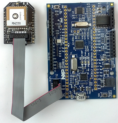
Connect the experiment board to the GPS module with the 14-pos IDC Ribbon Cable 50 mil that came with the GPS module like this:

The pin(s) are specified in the mbed library with the actual pin names as well as some useful aliases:
| Schematic Name | mbed Pin Name | Arduino Shield Alias | Description |
|---|---|---|---|
| PIO0_0 | P0_0 | D0 | UART RX |
| PIO0_4 | P0_4 | D1 | UART TX |
2) Description
The Global Positioning System (GPS for short) is a satellite navigation system that provides time and location information as long as there is a direct line of sight to at least four satellites. GPS is used in a wide range of application including cell phones and car navigation systems.
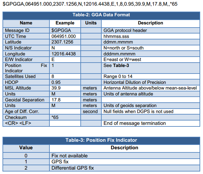
The module outputs a number of different messages in the NMEA 0183 format (http://en.wikipedia.org/wiki/NMEA_0183). Each message starts with a dollar sign $ and ends with a checksum. These are some examples taken from the manufacturer’s data sheet:
$GPGGA,064951.000,2307.1256,N,12016.4438,E,1,8,0.95,39.9,M,17.8,M,,*65

$GPGSA,A,3,29,21,26,15,18,09,06,10,,,,,2.32,0.95,2.11*00

$GPGSV,3,1,09,29,36,029,42,21,46,314,43,26,44,020,43,15,21,321,39*7D

$GPRMC,064951.000,A,2307.1256,N,12016.4438,E,0.03,165.48,260406,3.05,W,A*2C
The exact meaning of each of them is found in the data sheet but here we will focus on the one starting with $GPGGA as it contains the time and location information.

The following program is a very basic implementation of a parser of the data from the GPS.
main.cpp
#include "mbed.h"

Serial pc(USBTX, USBRX); // tx, rx
Serial uart(P0_4, P0_0);

/**
* Data structure for the GPS values
*/
typedef struct gpsData {
    uint8_t satellitesUsed[20];
    uint8_t utcTime[20];
    uint8_t altitude[20];
    uint8_t bufLatitude[20];
    uint8_t bufLongitude[20];
    int positionFixed;
    int northSouthIndicator;
    int eastWestIndicator;
    int latitude;
    int longitude;
} gpsData;

static uint8_t END_OF_MESSAGE = '\0';
static uint8_t DIVIDER = ',';

// The parsed data
static gpsData data;

/*****************************************************************************
** Function name: hasPattern
**
** Descriptions: Tests if pBuf starts with pPattern.
**
** parameters: Buffer to search and pattern to match
** Returned value: 1 if pBuf starts with pPattern, 0 otherwise
**
*****************************************************************************/
static uint8_t hasPattern(uint8_t *pBuf, uint8_t *pPattern)
{
    while(*pBuf != END_OF_MESSAGE && *pPattern != END_OF_MESSAGE) {
        if(*pBuf != *pPattern) {
            return 0;
        }
        pPattern++;
        pBuf++;
    }
    return 1;
}
/*****************************************************************************
** Function name: pointToNextValue
**
** Descriptions:    Moves past the next divider
**
** parameters: Pointer to the string to search
** Returned value: None
**
*****************************************************************************/
static void pointToNextValue(uint8_t **ppBuf)
{
    while(**ppBuf != END_OF_MESSAGE) {
        if (**ppBuf == DIVIDER) {
            (*ppBuf)++; // point to the start of next value
            break;
        }
        (*ppBuf)++;
    }
}
/*****************************************************************************
** Function name: convertCordinateToDegree
**
** Descriptions: Converts the pBuf string which is in the
** "ddmm.mmmm" format into an integer representation
**
** parameters: The buffer, the resulting integer and the
** length of the buffer
** Returned value: None
**
*****************************************************************************/
static void convertCordinateToDegree(uint8_t *pBuf, int* pDegree, int len)
{
    int index = 0;
    int sum = 0;
    int deg = 0;
    int min = 0;
    int div = 0;
    int pow = 1;
    for (index = len; index >=0; index--) {
        if (pBuf[index] == '.') {
            div = 1;
            continue;
        }
        sum += pow * (pBuf[index] & 0x0F);
        if (index > 0) {
            pow *= 10;
            div *= 10;
        }
    }

    div = pow / div;
    deg = sum / (div*100);
    min = sum - (deg*div*100);

    // convert to decimal minutes
    min = (min * 100) / 60;
    *pDegree = (deg*div*100) + min;
    if (div > 10000) {
        // normalize minutes to 6 decimal places
        *pDegree /= (div / 10000);
    }
}
/*****************************************************************************
** Function name: parseUTC
**
** Descriptions:    Extracts the UTC time string in hhmmss.sss,
** ignoring the .sss part and stores the result
** as a string in data.utcTime.
**
** parameters: The buffer
** Returned value: None
**
*****************************************************************************/
static void parseUTC(uint8_t **ppBuf)
{
    int index = 0;
    // parse utc hhmmss.sss
    while(**ppBuf != END_OF_MESSAGE) {
        if(**ppBuf == '.') {
            pointToNextValue(ppBuf);
            break; //reached end of the value
        }
        data.utcTime[index++] = **ppBuf;
        if(index == 2 || index == 5) {
            //Add divider
            data.utcTime[index++] = ':';
        }
        (*ppBuf)++;
    }
    data.utcTime[index] = '\0';
}
/*****************************************************************************
** Function name: parseLatitude
**
** Descriptions: Extracts the latitude information and stores
** the result as an integer in data.latitude.
**
** parameters: The buffer
** Returned value: None
**
*****************************************************************************/
static void parseLatitude(uint8_t **ppBuf)
{
    int index = 0;
    while(**ppBuf != END_OF_MESSAGE) {
        if (**ppBuf == DIVIDER) {
            (*ppBuf)++; //reached end of the value
            break;
        }
        data.bufLatitude[index++] = **ppBuf;
        (*ppBuf)++;
    }
    convertCordinateToDegree((uint8_t *) &data.bufLatitude, &data.latitude, 8);
}
/*****************************************************************************
** Function name: GPSRetreiveData
**
** Descriptions: Reads and parses the next set of GPS data.
**
** parameters:  None
** Returned value: The parsed information
**
*****************************************************************************/
const gpsData* GPSRetreiveData(void)
{
    uint8_t * pattern = (uint8_t*)"GPGGA";
    while (1) {
        uint8_t buf[100];
        uint8_t ch = 0;
        uint8_t *ptr = 0;
        int index = 0;

        // Retrieve the first byte
        //if (!UARTGetChar(&ch))
        //    continue;
        ch = uart.getc();

        // look for "$GPGGA," header
        if (ch != '$') {
            continue;
        }

        // Retrieve the next six bytes
        for (index=0; index<6; index++) {
            buf[index] = uart.getc();
        }

        //Check if its Global Positioning System fixed Data
        if (hasPattern((uint8_t*)&buf, pattern) == 0) {
            continue;
        }

        //Retrieve the data from the GPS module
        for (index=0; index<100; index++) {
            buf[index] = uart.getc();
            if (buf[index] == '\r') {
                buf[index] = END_OF_MESSAGE;
                break;
            }
        }
        ptr = &buf[0];

        //parse UTC time
        parseUTC(&ptr);

        //parse Latitude
        parseLatitude(&ptr);
        break;
    }
    return &data;
}

int main (void)
{
    //initialize the UART to 9600bps 8N1
    uart.baud(9600);
    //uart.format(8, Serial::None, 1);

    pc.printf("Waiting for GPS data...\n");

    //enter forever loop
    while(1)
    {
        const gpsData* pData = GPSRetreiveData();
        displayGpsData(pData);
        wait(1);
    }
}
Create your own program based on the code skeleton above. You will have to implement the displayGpsData() function to display the gathered data. Note that only UTC time and latitude is being parsed.
Run the program to see the current time and latitude. The latitude settings requires at least four satellites, so if the latitude remains 0 after a minute then move closer to a window or perhaps take the board outside.
Extend the program by implementing the functions to at least extract longitude and number of satellites.
Verify your result by entering the coordinates in for example Google Maps or http://www.findlatitudeandlongitude.com/find-address-from-latitude-and-longitude/.
3) Description
Embedded Artists has published a library that handles all of the GPS parsing and does so with a cleaner interface:
Import library
Public Member Functions |
|
| MTK3339 (PinName tx, PinName rx) | |
|
Create an interface to the
MTK3339
GPS module.
|
|
| void | start (void(*fptr)(void), int mask) |
|
Start to read data from the GPS module.
|
|
| template<typename T > | |
| void | start (T *tptr, void(T::*mptr)(void), int mask) |
|
Start to read data from the GPS module.
|
|
| void | stop () |
|
Stop to read data from GPS module.
|
|
| NmeaSentence | getAvailableDataType () |
|
Get the type of the data reported in available data callback.
|
|
| double | getLatitudeAsDegrees () |
|
Get latitude in degrees (decimal format)
|
|
| double | getLongitudeAsDegrees () |
|
Get longitude in degrees (decimal format)
|
|
Data Fields |
|
| GgaType | gga |
|
Time, position and fix related data.
|
|
| VtgType | vtg |
|
Course and speed information relative to ground.
|
|
Import the library and add a main.cpp like this:
main.cpp
#include "mbed.h"
#include "MTK3339.h"

static int waitData = 0;
static MTK3339 gps(P0_4, P0_0);

static void dataAvailable() {
    waitData |= gps.getAvailableDataType();
}

int main(void) {

    gps.start(&dataAvailable, (MTK3339::NmeaGga|MTK3339::NmeaVtg));

    while(1) {
        while(waitData == 0);

        if ((waitData & MTK3339::NmeaGga) != 0) {
            waitData &= ~(MTK3339::NmeaGga);
            printf("gpa: fix=%d, sats=%d, alt=%f, lat=%f, lon=%f\n",
                gps.gga.fix, gps.gga.satellites, gps.gga.altitude,
                gps.getLatitudeAsDegrees(), gps.getLongitudeAsDegrees());
        }
        if ((waitData & MTK3339::NmeaVtg) != 0) {
            waitData &= ~(MTK3339::NmeaVtg);
            printf("vtg: course=%f, speed=%f km/h, mode=%c\n",
                gps.vtg.course, gps.vtg.speedKmHour, gps.vtg.mode);
        }

        waitData &= (MTK3339::NmeaGga|MTK3339::NmeaVtg);
    }
}
As you can see the GPS library will notify you by calling dataAvailable() when a new string has been received from the GPS.
A lot of information is printed in the example above and perhaps it is not the way you like it. Look at the gga and vtg structures described in the MTK3339.h files and then modify the program to only print the UTC time and longitude/latitude.
If you want to to work more with the GPS a suggestion is to go back to the 7-segment lab and use that to display the number of satellites.
When you have completed the Character LCD experiment you can use that to show the current time.
Solution(s)
Import programlpc812_exp_solution_exp-port-xbee
Solutions for the XBee experiments for LPC812 MAX
Import programlpc812_exp_solution_exp-port-gps
Solutions for the GPS experiments for LPC812 MAX
Import programlpc812_exp_solution_exp-port-gps-lib
Solutions for the GPS with MTK3339 lib experiments for LPC812 MAX
Please log in to post comments.
