m3pi Development
After playing the the 3pi, I had a list of things I want to achieve and add to the 3pi. The ideas below are just driven by my objectvies and irritations
- An "m3pi" library class that abstracts all the features and functions of the basic 3pi to simple method calls. (controlling motors, LCD, speaker, line following sensors)
- An eagle library for the expansion card template, and a refernce design to be publushed and reused. Alex has kindly shared his work on this.
- A battery charger on the expansion card, to charge NiMH cells fitted into the 3pi. My idea here was to have the batteries charged by USB (or some other DC source) whenever is is plugged
- Footprints for common, low cost wireless modules (Bluetooth, Zigbee, Wifi)
- Use a SPI port on the mbed to reflash the ATMega328 from the mbed LocalFileSystem (drag and drop programming for the ATMEga!). I'll reuse the AVR910 implementation from Aaron Berk
Getting Started
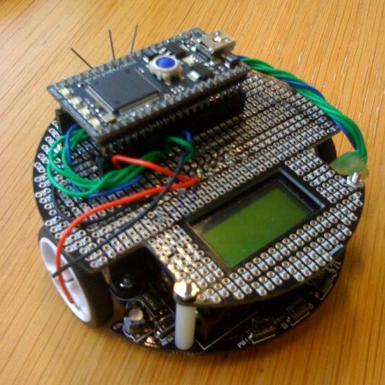
Before I go headlong into making a PCB, I want to prototype it all up, so I bought an expansion card, and built this :
Getting Stuck In
After playing a little bit with Chris prototype, I start working with the charging circuit.
A Linear IC selected for this job as it was the best fitted solution because of the lowest count in peripheral components with the shortest time from concept to production. I populate the design with the footprints of the mbed, Bluetooth and XBee modules, together with a row of eight LEDs (Yes, we can create some funny scroll messages with those!!!).
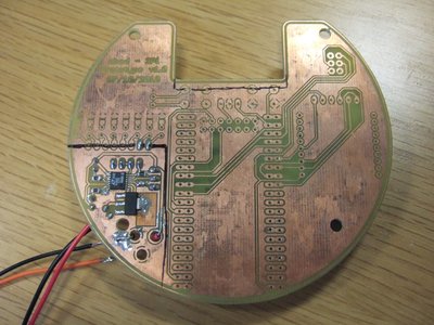
The PCB produced using the etching method. I know that it looks ugly but it was my first one using the local equipment. It is a process that demands good timings counted in seconds with these powerful chemicals. At least we can test the parts that we want really easily…
(I am promising for an easy step by step tutorial of how you can make your own PCBs with this method, using simple products from your local super market and not the dangerous and aggressive chemicals)
And here is a close up of the actual charging circuit.
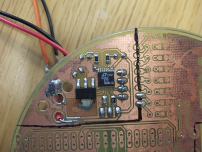
Check the color difference in the square just below the transistors collector. This indicates the expected heat produced by the high current flow. If we reduce the charge current and increase the PCB heat sink we will have a safer implementation for the user (and that is what we are planning to do in the next prototype, together with a few more improvements.
The testing procedures were in this bench, together with the discharge element… yes, a small value resistor!
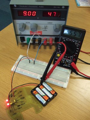
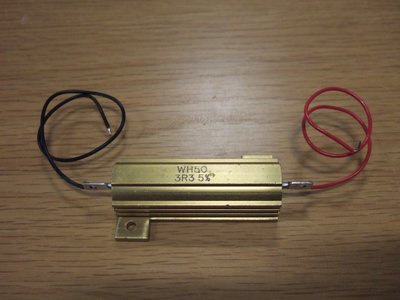
The circuit consumes 470mA @ 9V making it perfect for a wall powered transformer and medium capacity batteries.
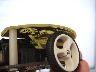
And here is a small mechanical problem. This pin header is aligned just 2mm above the 3pi wheel. Yes, I am already making a few changes in the next prototype… so, stay tuned!!!
Updates... (26/10/2010)
Yeah!!! We’ve made lot of steps ahead and I am posting in order to update the mbed community! The software and hardware parts are on extensive testing, the custom made PCBs will be in our hands in few days and the team is really exited!!! I will upload more photos tomorrow and of course from the full process starting with the box opening of the PCBs to the assembly process... but for now, some photos from the early prototype state.
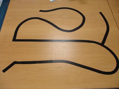
First the track! Yes, it is made using a black electrical tape on the surface of a spare desk inside the mbed team office. It looks great if you consider that it takes 20 seconds to build one of those (spending less than one pound).
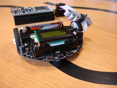
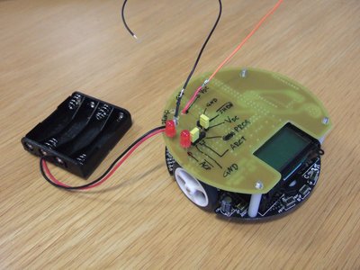
And here is one of our test robots (mainly designed for software testing). We build it using a fast prototype PCB (very common technique in the fast production field). It includes an mbed as well as an IDC connector for In Circuit Programming of the 3pi.
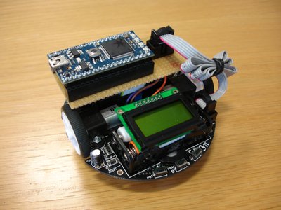
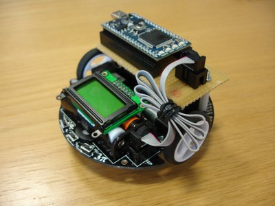
But don’t worry! If you are an mbed user you don’t have to learn a new programming language or any sophisticated / time consuming / boring technique in order to work with the robot platform. We finalizing an API for the mbed - 3pi and that will make the coding process really easy (don’t forget... this is the power of the mbed!!!).
Resources
- m3pi page
- 3pi schematics
- The 3pi Eagle library - Note, this isnt tested properly yet
- The mbed socket Eagle library
- Some wiring notes from the AVR910 docuement
- The Roving Networks RN42 bluetooth module, which luckily enough has an Eagle symbol and footprint in the Sparkfun Eagle Library
- Data sheet for the PNA4602 38kHz IR sensor