MultiTech Dragonfly Nano
The MultiConnect® Dragonfly Nano offers developers an FCC and carrier certified solution that makes connecting sensors and other edge-of-network devices quick and easy.
Overview
The MultiConnect® Dragonfly™ Nano cellular SoMs are complete, ready-to-integrate processing and communications devices that offer developers the functionality of a SoM with the convenience of an onboard cellular radio all in one compact design. With its integrated Cortex M4 processor, developers can host their application and have access to a full suite of interfaces for connecting sensors or other remote assets.
Key Benefits
- End device certified by leading carriers
- Low power modes extend life of battery powered devices
- Extended coverage means assets deep inside buildings are now reachable
- Long solution lifecycle reduces redesign time and cost
- LTE, Cat M1
Features
- 3GPP Release 13 Extended Discontinuous Reception (eDRX)
- 3GPP Release 13 Extended Coverage
- 3GPP Release 12 Power Saving Mode (PSM)
- Arm® Mbed™ OS enabled
- Multiple I/O interfaces for connecting almost any “Thing”
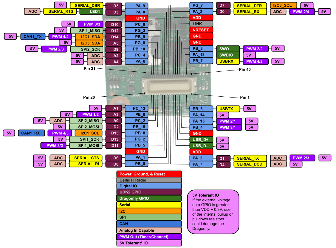
Dragonfly Nano Pinout Diagram
- The pinout diagram shows the commonly used interfaces and their locations. In addition to their stated functions, all GPIO pins (PA_*, PB_*, PC_*, PG_*) can be used as general purpose I/Os. See the STM32L471 documentation for additional pin multiplexing options.
Pinout definition spreadsheet
Dragonfly Nano Features
- STM32L471QG Processor
- Ultra Low Power ARM® Cortex™-M4 Core
- 80 MHz,128 KB SRAM, 1MB Flash
- SPI (2)
- I2C (2)
- UART(1)
- PWM (12)
- ADC (9)
- GPIO (29)
- Ublox Cellular Radio
- Connected to Processor via UART
- TCP & UDP Sockets
- SMS messaging
- Micron M25P16 Flash Memory
- 16Mb serial flash
- 16Mb serial flash
Getting Started
1. You will need a Developer Kit
MTUDK2 Developer Kit home page
MTUDK2 developer guide
Legacy MTUDK2 Developer Kit home page
Legacy MTUDK2 developer guide
- From the developer kit home page download and install the MTUDK2 USB Driver.
- Refer to the instructions in the MTUDK2 developer guide for installation instructions.
2. Attach to your PC
- Plug your PC into the MTUDK2 USB port and your PC should recognize the MTUDK2 and Dragonfly Nano as a USB drive with the name MULTITECH. This will take a few seconds.
- This works out of the box for Linux, macOS and modern Windows versions. Windows 7 serial driver information can be found here.
3. Programming the Dragonfly Nano
- Download, then drag and drop this example blinky program onto the recognized USB drive. The MTUDK2 STAT and COM leds will flash alternately as the program is loaded. Once loaded, the MTUDK2 D3 led will flash.
- blinky example page
4. Start developing with mbed
mBed studio
If you develop with mbed studio see 'Limitations & Issues' below.
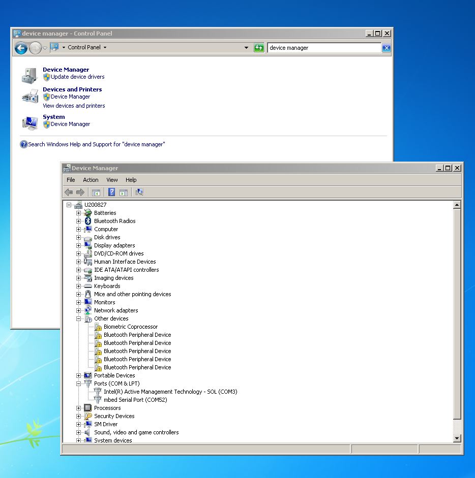
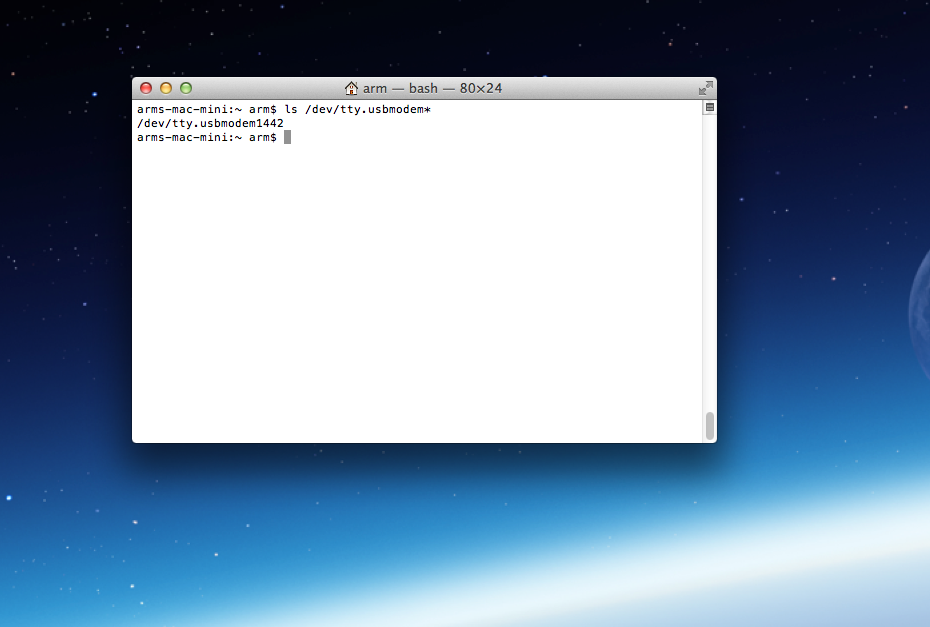
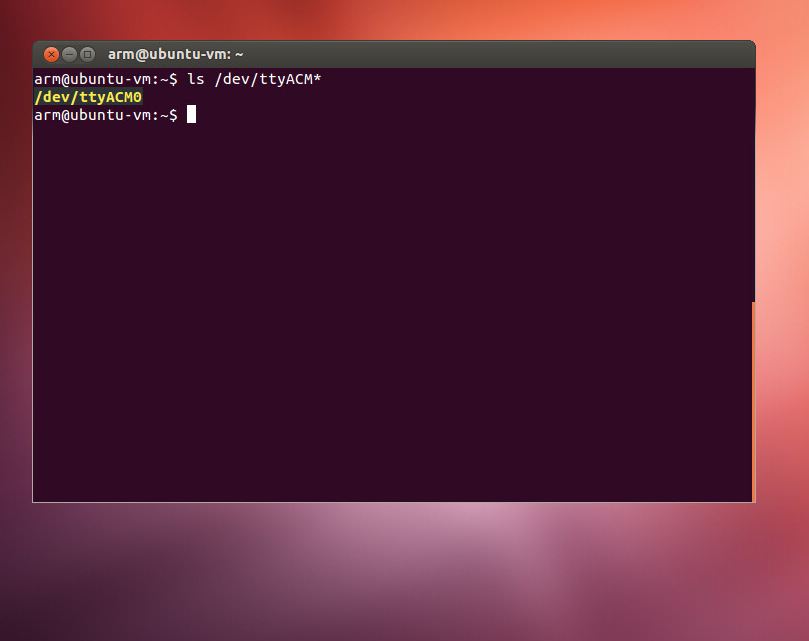
5. More on serial ports
Some terminal programs (e.g. TeraTerm) list the available serial ports by name. However, if you do need to know the identity of the serial port so that you can attach a terminal or an application to it:
Example Programs
Example programs can be used to quickly get up and running with Dragonfly Nano. Please read through the documentation included with the example applications.
Official mbed cellular example
mbed-os version
At the time of this writing, the Official mbed cellular example calls for mbed-os vs 6.5. There are a couple pending mbed-os pull requests on github that should be available in the next mbed release.
- 13935 - This implements radio reset on soft_power_on() and improves power on/off.
- 13998 - This adds the ability to retrieve crash reporting information and perform auto-reboot on hard faults.
Differences vs official example
- Example loops with 10s sleep demonstrating low power
- Uses RTC back registers to store information over reset
- Implements crash reporting and auto-reboot
- Uses mbed-os-6.6.0 which includes pull requests 13935 and 13998
Official Mbed OS example for AWS cloud using mbed-client-for-aws
Please see official mbed examples
Limitations & Issues
1. mbed Studio does not recognize the Dragonfly Nano
- By default, MTUDK2 development boards return the Dragonfly ID rather than the Dragonfly Nano. There are two ways to remedy this.
1. Change the device ID the MTUDK2 reports to the PC
- Download the ST-LINK driver
- Once you have installed it, run 'st-LinkUpgrade.exe -force_prog -board -0312' to program the interface chip on the MTUDK2 as MTS_DRAGONFLY_L471QG.
- NOTE: To change it back, run 'st-LinkUpgrade.exe -force_prog -board -0310'
2. Change the device ID the PC associates with ID 0310, use the mock command on the mbed-cli command line
mbedls --mock 0310:MTS_DRAGONFLY_L471QG- NOTE: To change it back enter:
mbedls --mock 0310:MTS_DRAGONFLY_F411RE
2. Possible connectivity issues due to PDP type
Mbed queries the cellular radio PDP context looking for a PDP type and APN match. You might need to adjust the PDP type that mbed accepts for this platform. In the file mbed-os/connectivity/drivers/cellular/MultiTech/DragonflyNano/PPP/SARA4_PPP.cpp, there are settings for PROPERTY_IPVx_STACK. In our testing, we have found that enabling only IPV4V6 works for all the SIM cards we have tested. If you have experiencing connectivity problems, you may want to enable IPV4 or IPV6. If you suspect such a problem it is suggest to enable debug messages.
To aid with debugging
Enable log messages in mbed_app.json
- set "mbed-trace.enable": true
- set "cellular.debug-at": true
- change "trace-level" to increase or decrease log message level
3. InterruptIn Limitations
Due to the processor's architecture, only one pin of the same number (e.g. PA_1 & PB_1) may be configured as an InterruptIn. If multiple pins of the same number are configured as InterruptIn, only the last pin configured will actually trigger an interrupt in the processor. The rest will be ignored.
4. PwmOut Limitations
PwmOut objects using different channels of the same timer must use the same prescaler value. Each timer has a single prescaler which applies to all channels in the timer.
For STM32L471 devices, two possible prescaler values are allowed:
- 1us which allows for a period/pulse from 1us to 65535us
- 500us which allows for a period/pulse from 500us to 32.76s
5. 5V Tolerant IO Limitations
If the external voltage on a GPIO is greater than VDD + 0.3V, use of the internal pullup or pulldown resistors could damage the Dragonfly Nano. External pullup or pulldown resistors should be used instead.
For more information see the notes below section 6.3.1 of the STM32L471QG Data Sheet.
6. Developer Kit target ID issue
- By default, MTUDK2 development boards identify target devices as MTS_DRAGONFLY_F411RE. To run Mbed OS automated tests or perform debug, you need to either mock or change the device ID to MTS_DRAGONFLY_L471QG.
1. Change the device ID the MTUDK2 reports to the PC
- Download the ST-LINK driver
- Once you have installed it, run 'st-LinkUpgrade.exe -force_prog -board -0312' to program the interface chip on the MTUDK2 as MTS_DRAGONFLY_L471QG.
- NOTE: To change it back, run 'st-LinkUpgrade.exe -force_prog -board -0310'
2. Change the device ID the PC associates with ID 0310, use the mock command on the mbed-cli command line
mbedls --mock 0310:MTS_DRAGONFLY_L471QG- NOTE: To change it back enter:
mbedls --mock 0310:MTS_DRAGONFLY_F411RE
Technical References
Dragonfly Nano: manuals, data sheets and drivers etc.
Radio AT commands
STM32L471QG
Micron M25P16 flash memory
Developer kit: manuals, quick start and driver
Factory Firmware
The Dragonfly Nano ships from the factory pre-loaded with AT pass through firmware. This firmware implements serial passthrough providing AT command access to the cellular radio via the MTUDK2 developer board or directly through the USB connector on the Dragonfly Nano
Bootloader
If you would like to use a bootloader with your application, there is one available for the Dragonfly Nano found here. The bootloader stores the new image for upgrade and the old image as a back up in the on board flash memory during firmware upgrade. The on board flash memory is 2MB. The STM32L471 flash space is 1MB. So the back up file consumes half the flash space. The flash file system used on the flash part consumes several hundred KB of space. So the new image is limited to the remaining flash space. If other files are placed in flash, there will be even less space available.
Interface Firmware
- The MTUDK2 uses the same ST-Link interface firmware as many of the ST Nucleo boards. The latest interface firmware and instructions for upgrading can be found here.
Support
You need to log in to post a discussion
Discussion topics
| Topic | Replies | Last post |
|---|---|---|
| device_ID, Dragonfly Nano, mbed, Mbed Studio Anyone noticed that mbed Studio does not properly recognize the Dragonfly Nano? | 1 |
08 Aug 2019
by
|
Questions
5 years, 4 months ago
