Need help with SPI com

10 Jan 2011

Hello,

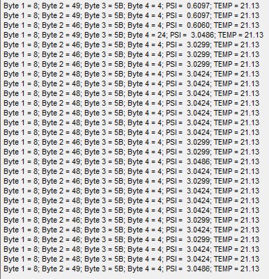
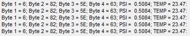
I need to communicate with a Honeywell pressure sensor over the SPI bus, but I am not familiar with the SPI bus at all.

Can anyone tell me how to read the pressure, or at least explain what I need. This is a link the SPI information but it seems incomplete to me.

http://sensing.honeywell.com/index.cfm/ci_id/156989/la_id/1/document/1/re_id/0

Thanks


11 Jan 2011

Hi,..

I did the same thing a few weeks ago, where I needed to learn SPI.

There are plenty of libraries in the cook book that use SPI to talk to devices.

I understood one of those first, have a look at them and read the SPI class documentation.

Tbh, all the hard work has been done for you, all you have to find out is how to read the output bytes and set the clock speed. (iirc).

I'm rubbish at bitwise operators, but it looks like that puts out 4 bytes, and you have to drag the value out of the middle of that. (I had to drag 11 bits out of 2 bytes, and they held the value 2's complement, I needed help with that)

Have a read of the ones in the cookbook, and disregard most of that datasheet.

(btw,.. looks very complete to me, almost too complete for your purposes)


11 Jan 2011

Thanks for the reply, but I still don't get it.

You say the data sheet looks complete be there are no addresses specified, for example,

register_name &= 0xFC; //Read command

Am I to assume that all SPI devices use 0xFC as the Read command?

At what address do I read the pressure and what address do I read the temp?

Seems to me that a sensor could simply output the pressure in psi or bar or something, what is the purpose for all the calculations and shifting bits after you extract the data?


11 Jan 2011

Hi!

This device seems to have no addresses!

Just read 2 Bytes from the device with spi and you should get the pressure:

"To read out a compensated pressure reading, the master generates the necessary clock signal after activating the sensor with the slave select line. The sensor will transmit up to 4 bytes of data – the first two bytes containing the compensated pressure output,..."

Use the spi.write command with a dummy-write data as done in the SPI-Handbook-example ( spi.write(0x0000);)

http://mbed.org/handbook/SPI

Dont't forget the SlaveSelect(SS)= ChipSelect-Line!

Hope this helps

Charly

11 Jan 2011

Thanks, I think I am getting the right info now, I just need to figure out the formulas. However the data sheet for this specific device says nothing about the max output counts.


12 Jan 2011

[quote]

This device seems to have no addresses![/quote]

That can't be right because changing the dummy value changes the output received. Also, the value never changes regardless of pressur on the sensor.

So I am still missing something.


12 Jan 2011

Hi !

Can you post your code here and the values you get from the sensor?

Some things to consider:

  • what are the values of the returned status-bits S1 and S0 ?
  • do you read 2,3 or 4 Bytes from the sensor?
  • do you wait a short time after lowering the ss-line and before the spi.write() ? THDSS in the specs
  • is the device in command-mode? -> no info in the specs about how to get in and out of this!
  • did you connect the mbed-mosi-line? Should not be connected, and there goes the spi.write() value
  • is the sensor connected correctly to the mbed-spi-interface?
  • is the mbed-spi-interface correctly initialized?

Regards - Charly

12 Jan 2011

My current Code


#include "mbed.h"
#define OUT_MAX 2104
#define OUT_MIN 1632
#define PRES_MAX 5
#define PRES_MIN 0

SPI spi(p5, p6, p7); // mosi - no connection, miso - connected to pin 3 of sensor, sclk connected to pin 4 of sensor
DigitalOut cs(p8);   // chip Select line connected to pin 5 of sensor

Serial pc(p13,p14); // tx, rx

int main() {
    // Setup the spi for 8 bit data with a 800KHz clock rate
    spi.format(8,0);
    spi.frequency(800000);

    while(1)
    {
    // Select the device by seting chip select low
    cs = 0;
    wait(0.1);
    // Send a dummy byte to receive the contents
    int byte_1 = spi.write(0x00);
    int byte_2 = spi.write(0x00);
    int byte_3 = spi.write(0x00);
    int byte_4 = spi.write(0x00);
    
    float temp = byte_3<<3;
    temp = ((temp/2047)*200)-50;
    float psi = byte_1<<8|byte_2;
    //psi = byte_1|byte_2;
    psi = ((psi-OUT_MIN)*5)/(OUT_MAX-OUT_MIN);
    
    pc.printf("Byte 1 = %X; Byte 2 = %X; Byte 3 = %X; Byte 4 = %X; PSI =  %.4f; TEMP = %.2f\r",byte_1,byte_2,byte_3,byte_4,psi,temp);
    
    // Deselect the device
    cs = 1;
    wait(0.5);
    }
}


And my results;

data

The TEMP is fairly close. it is of by 2 degrees (I'm only using byte 3), but I assume the inside of the chip is warmer than the outside air.

The PSI is somewhat close, but not right. (This is a 0 to 5 psi sensor BTW, http://sensing.honeywell.com/index.cfm/ci_id/156218/la_id/1/document/1/re_id/0 )

I'm fairly sure I don't have the math correct, but I don't know what the OUTPUTmin and OUTPUTmax are supposed to be. I tried using the 2^14 but thats way off. If I use the value at 0 psi for OUTPUTmin and then use the value at 5 psi for the OUTPUTmax I can get it close but still varies wildly (as in the current code) - so I don't think that is right as it is not very accurate to even call it a sensor.

So I am still missing something here.

Thanks for your help, much appreciated.

12 Jan 2011

One thing I think is not correct is the clock polarity and phase. In the document you referred, it is stated that

For the temperature, try to change your calculation to

(temp*200/2047)-50

This way you avoid getting a small number in the first calculation step, which might result in a loss of precision (though I think that it should not be 2 degrees off).

Regarding the pressure readings: are you using a gage pressure sensor? (These are the only ones at Honeywell which are available as 5 psi version, e.g. *005PG*).

The data sheet states for these that the output is relative to the current atmospheric pressure, so it is not constant. Pmin is the atmospheric pressure, which means on open air the output from the sensor should be zero. The maximum value (16383) should be reached with 5 psi. So your OUT_MAX should be 16383, not 2104.

On the other hand, the example on the top right corner of page 5 state that these readings should be 10% (1638) and 90% (14745), respective. You might need to experiment a little bit...

13 Jan 2011 . Edited: 13 Jan 2011

I wondered about the Clock Polarity as well, I will check again in the morning but I am sure I tried all the settings, 8,0 8,1 8,2 and 8,3.

I have tried the clock at 800k, 80k, 100k 8k all the same thing.

I believe the temp is the temperature of the sensor itself and not the ambient air temp, so I think that will be off a bit from the air temperature - but then again at this point I'm not sure about anything.

Yes, it is a guage sensor. I have both a 0 to 1 psi and a 0 to 5 psi and I get about the same results from both. I can put 5 psi on the sensor and it only changes by about 500 counts - to me thats not right.

The digital output count has never been 0.0 even at 0 pressure and even a slight vacuum on the port. I have tried OUTPUT_max at 16383, that makes it even further out of wack - I have tried all kinds of numbers lol.

I don't think I am reading the data correctly. Am I getting all 4 bytes in the right manor? Should I be getting all 4 bytes in one word - all at once instead of using 4 spi.writes?


13 Jan 2011

When the count changes only by 500 when you change the pressure something is wrong. In my experience it is most likely that either the SPI format is something else then you think, or the specified format is wrong (most likely the latter).

Also, it might be better to read all values within one SPI read. The data sheet specifies a minimum SPI clock rate (50 kHz), so you cannot have too long delays between clock cycles. Doing 2 reads might cause that, and therefore lead to your wrong reading. You could try to read 16 bits for a start, I'm not sure how many bits the SPI read can handle.

13 Jan 2011

Hi!

I wonder about the output! On the first line you get

  • byte 1: 8 Byte 2: 49

and on the last you also get

  • byte 1: 8 Byte 2: 49

But you get two different psi-outputs!

This doesn't fit to your code!

But I can't see the error :-(

On the first hit, I would try to only read 2 Bytes with one spi.write() and see what comes out:

...
spi.format(16,3);
...
int return_value = spi.write(0x0000);

BTW: Reading with two 8-bit spi.write() values should work also!

Regards Charly

13 Jan 2011

@Hendrik,

Quote:

the data should be captured on the falling edge (chapter 2.0)

This is incorrect. Chapter 2 Figure 2 shows the data is sampled on the rising clock edge.

The same Figure 2 also shows the clock idle state high. This therefore suggests the CPOL should be 1 and CPHA should also be 1. However, Figure 3 SPI bus timing shows the sclk low when SS assert which suggests CPOL should be zero and CPHA should be zero. So you might like to try spi.format(8,0); and spi.format(8,3);. I susspect you will get the same results as the important factor is the bit data is latched on the rising sclk edge.

Quote:

Also, it might be better to read all values within one SPI read. The data sheet specifies a minimum SPI clock rate (50 kHz), so you cannot have too long delays between clock cycles. Doing 2 reads might cause that, and therefore lead to your wrong reading. You could try to read 16 bits for a start, I'm not sure how many bits the SPI read can handle.

This is also incorrect. The sclk frequency on an SPI bus is "burst frequency". The sclk on an SPI bus is always high or low between accesses (depends on CPOL and CPHA as to which). You should stick with 8 bit transfers as this is what the data sheets/tech note is saying.

@Glenn,

The datasheet does say that the sclk should be between 50kHz and 800kHz. I see you are using the maximum. Try using something a bit more moderate like 100kHz to start with. It just maybe your setup isn't quite right to run at the datasheets max clock rate.

What is the part number of the Honeywell device you are using?

13 Jan 2011

I wonder about the output! On the first line you get

  • byte 1: 8 Byte 2: 49

and on the last you also get

  • byte 1: 8 Byte 2: 49

But you get two different psi-outputs!

That because I was playing with the numbers. The results you see above my be a capture of several different changes.

I have tried everything suggested here so far and nothing seems to work. I don't believe that the sensors are bad, I have 4 of them, 2 are 0 to 1 psi (HSCDANN001PGSA5) and 2 are 0 to 5 PSI, (HSCDANN005PGSA5) All 4 of them show similar results. I can not locate specific data sheets for each part, only in general that covers the HSC series.

This sheet, http://sensing.honeywell.com/index.cfm/ci_id/157750/la_id/1/document/1/re_id/0 shows what the digital counts should be, and at 0 psi I have 0x0681


The datasheet does say that the sclk should be between 50kHz and 800kHz. I see you are using the maximum. Try using something a bit more moderate like 100kHz to start with. It just maybe your setup isn't quite right to run at the datasheets max clock rate.

I have tried everything all the way down to 50Khz, no luck. I have tried changing the SPI to pins 11,12, and 13 - same results. I'm sure I am doing something wrong, I just don't know what. Everything I have read says I don't need pull-ups or anything like that. Changing the spi.format has no effect on the resutls what so ever except 8,2 which send it way off base. Changing it to 16 bit didn't make any differance either.

I currently use Analog sensors which are quite accurate, I guess I should just stick with them.

Thanks everyone for you help and suggestions.

13 Jan 2011

Andy K wrote:

Quote:

the data should be captured on the falling edge (chapter 2.0)

This is incorrect. Chapter 2 Figure 2 shows the data is sampled on the rising clock edge.

This was actually what I meant to write - when you read further you see that I came to the same conclusions regarding CPOL/CPHA.

Andy K wrote:

So you might like to try spi.format(8,0); and spi.format(8,3);. I susspect you will get the same results as the important factor is the bit data is latched on the rising sclk edge.

I think they will differ. As wikipedia states, these formats not only differ on which edge they sample (rising / falling), but also on which edge they start. So Glenn should really try all formats, especially since the data sheet is not really clear here.

Andy K wrote:

Quote:

Also, it might be better to read all values within one SPI read. The data sheet specifies a minimum SPI clock rate (50 kHz), so you cannot have too long delays between clock cycles. Doing 2 reads might cause that, and therefore lead to your wrong reading. You could try to read 16 bits for a start, I'm not sure how many bits the SPI read can handle.

This is also incorrect. The sclk frequency on an SPI bus is "burst frequency". The sclk on an SPI bus is always high or low between accesses (depends on CPOL and CPHA as to which). You should stick with 8 bit transfers as this is what the data sheets/tech note is saying.

Figure 3 in the data sheet show clearly continouos reads (and, btw., shows SCLK=idle high, so its consistent with figure 2 - or do you mean figure 3 on the last page?). Circuits with anlog parts in them tend to use the SCLK for their internal workings, so they might do something wrong when SCLK gets too slow (e.g. most ADCs with SPI to this, and they get much more incorrect when SCLK is too slow). For example, in the small delay between 2 8bit-reads internal capacitors in the sensor might get discharged, resulting in reading which are too low. That's why I was suggesting reading all data in a single call.

Btw: I just saw the wait(0.1) after the chip select - I think this should be more like a wait_us(10). The data sheet says a minimum of 2.5 microseconds, waiting too long might also cause some misbehaviour of the analog circuits (though the data sheets says nothing here).

With purely digital devices the SPI timing is normally not critical, but with analog devices one should really try to stick to their specifications (esp. clock frequency and delays), becaise when they use the clock for their inner workings they might just misbehave otherwise.

13 Jan 2011

Hi Glenn,

Just saw you were still having problems. A thought; your part number suggests it is the 5v version (not the 3.3v version). How have you got it powered? Haven't followed the discussion so not sure if this is relevant or already discussed, but just incase.

Simon

13 Jan 2011

I think they will differ. As wikipedia states, these formats not only differ on which edge they sample (rising / falling), but also on which edge they start. So Glenn should really try all formats, especially since the data sheet is not really clear here.

As stated above, made no differance.

Btw: I just saw the wait(0.1) after the chip select - I think this should be more like a wait_us(10). The data sheet says a minimum of 2.5 microseconds, waiting too long might also cause some misbehaviour of the analog circuits (though the data sheets says nothing here).

Tried that too, no change.

Just saw you were still having problems. A thought; your part number suggests it is the 5v version (not the 3.3v version). How have you got it powered? Haven't followed the discussion so not sure if this is relevant or already discussed, but just incase.

It is powered by the USB +5 volts

13 Jan 2011

I think it is strange that changing the SPI format makes no difference - I would expect that with the wrong format you should get much more varying / strange reading then when the format is right. This is because with the wrong format the mbed reads the same moment the device changes the data, which should (normally) lead to some inconsistencies.

Do you happen to have some device like the Bus Pirate which allows debugging the SPI communication?

Also when interfacing the mbed with your device, how do you do the voltage level translation for the SCLK signal? Reading the data sheet the sensor seems to expect at least 4 volts for the high signal...

13 Jan 2011 . Edited: 13 Jan 2011

Hi,

since you are getting a count of 0x0681 (1665) with no pressure applied, which is quite close to the specified zero-pressure-value (1632) for this sensor, i would assume that your SPI reading is working well and is correct. So IMHO either your math is wrong somewhere (but i don't see an error there) or more probably your applied pressure is not as high as you expect it to be. I don't know your setup of course, but how are you setting up and measuring the pressure you apply? One thing to pay attention to is that with a gage sensor you have to apply x psi + atmospheric pressure to the port to actually measure x psi.

Kind regards
Neni

13 Jan 2011

Also when interfacing the mbed with your device, how do you do the voltage level translation for the SCLK signal? Reading the data sheet the sensor seems to expect at least 4 volts for the high signal...

I really thought you were on to something there as I keep forgetting that the mBed is a 3.3v device, I have it connected directly to the sensor.

So, I took a second sensor and plugged it into my Arduino Test board which is 5volts, I'll let the results speak for them self. Note the Arduino data is in Decimal and the mBed is in HEX

mBed results, 0 to 5 psi

data_mbed


Arduino results, 0 to 5 psi

data_arduino

The pressure isn't quite exact, but the Temp is.


13 Jan 2011

Glenn, I have to ask, which do you think is right, the Mbed or the Arduino? And if so how do you know?

I sent you a private message offering to look at it if you want to "donate one device to the cause" by sending me one of your pressure transducers. I have an SPI bus analysiser on my LA so I can read the bytes off the wire between the controller and the device. Up to you, let me know.

13 Jan 2011 . Edited: 13 Jan 2011

since you are getting a count of 0x0681 (1665) with no pressure applied, which is quite close to the specified zero-pressure-value (1632) for this sensor, i would assume that your SPI reading is working well and is correct. So IMHO either your math is wrong somewhere (but i don't see an error there) or more probably your applied pressure is not as high as you expect it to be. I don't know your setup of course, but how are you setting up and measuring the pressure you apply? One thing to pay attention to is that with a gage sensor you have to apply x psi + atmospheric pressure to the port to actually measure x psi.

I use a mini pump with a mechanical guage to apply 5 psi to the sensors, the counts only increase by about 400 to 500 counts. Not nearly enough. I can verify the psi by applying the same to my analogs. I can also verify the psi using water to pressurize the tube (no water touches the sensor), 27.6807 inches of water (vertical) is equal to 1 PSI

AtmosP isn't going to effect it that much.

13 Jan 2011 . Edited: 13 Jan 2011

@Andy

I don't think either one is right lol.

I just wanted to eliminate the chance the SCLK voltage wasn't right, but I get basically the same results with 3.3v or 5v

I'm probably doing something stupidly wrong here and I'm too frustrated to spot it.

EDIT:

Where to I check my PMs? I don't see it anywhere.


20 Jan 2011

Well, I guess I will put this aside for now. Honeywell hasn't gotten back to me yet and it seems we are all out of ideas.

Thanks for everyones help.

20 Jan 2011

Quote:

Where to I check my PMs? I don't see it anywhere.

They should arrive via your registered email address.

27 Sep 2012

Here's a working program.

// Test program to read Honeywell Differential Pressure Sensor HSCDRRN060MDSA3
// SPI interface (800khz max clock), 3.3 volt supply, -60mbar to +60mbar
#include "mbed.h"

Serial pc(USBTX, USBRX);
SPI device(p11, p12, p13);      // mosi - no connection, miso - connected to pin 3 of sensor, sclk connected to pin 4 of sensor
DigitalOut ss(p20);             // slave select connected to pin 5 of sensor

float convertPressure(unsigned int output)
{
    // output at min. pressure [counts]
    #define OUTPUT_MIN 0        
    // output at max. pressure [counts]
    #define OUTPUT_MAX 0x3FFF   
    // max. value of pressure range [mbar]
    #define PMAX 60             
    // min. value of pressure range [mbar]
    #define PMIN -60  

    return 1.0*(output - OUTPUT_MIN)*(PMAX - PMIN)/(OUTPUT_MAX - OUTPUT_MIN) + PMIN;
}

float convertTemperature(unsigned int output)
{
    return output*200.0/2047.0 - 50.0;
}

int main() {
    unsigned int response1; // first 16 bits of response
    unsigned int response2; // second 16 bits of response
    // Setup the spi for 16 bit data, mode 0 (clock polarity 0, data sampled at rising edge) 
    device.format(16,0);
    // Setup the spi to use 800KHz clock rate
    device.frequency(800000);
    ss = 1;

    while(1) {
        ss = 0;  // assert slave select     
        response1 = device.write(0x0000); // send dummy command to read response
        response2 = device.write(0x0000); // send dummy command to read response
        pc.printf("raw %X = %f mbar  temp = %f\n", response1, convertPressure(response1), convertTemperature(response2/32));
        ss = 1; // deassert slave select
        wait(0.2);
    }
}