You are viewing an older revision! See the latest version
lpc bootloader
Once you have created a prototype of your product, you may want to be able to use the developed code on a target MCU (NXP LPC1xxx) in situ in your end-application board.

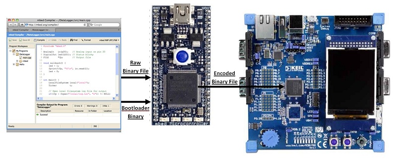
This page documents the development of a LPC1xxx bootloader program which makes the following process possible:
- The binary file to flash the target MCU with is placed on the mbed's local filesystem.
- The bootloader program is loaded onto the mbed's local filesystem and run, loading an encoded version of the binary file onto the LPC1xxx chip.
Chris Styles already experimented with bootloading NXP chips in Prototype to Hardware. This carries out the desired process, but makes use of the Flash Magic flash utility. This requires the user to convert the binary file into hex and then put it through the flash utility. Hence, the process could be streamlined by allowing binary files to be directly loaded, which is now possible using this bootloader program.
The Task Ahead
I started off by leafing through the UM10360 datasheet, which contains the information on the current evolution of the mbed (LPC1768). As always, you should start by reading from the very beginning (of page 615). This chapter looks at the flash memory interface and documents the In-System Programming (ISP) which is the serial communication path used for this bootloader. From reading through it, you gauge what is required:
Hardware (for the LPC1768):
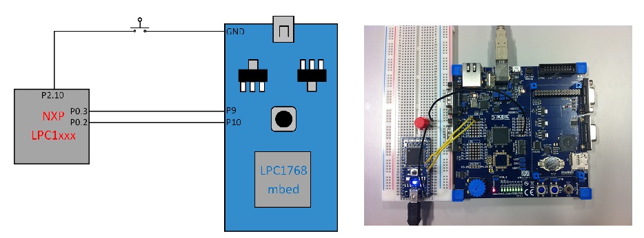
- In order to start the chip up in ISP bootloader mode, you need to breakout P2.10 and pull it low when resetting the board, for at least three milliseconds (possibly with a push button).
- Connect P9 of the mbed to P0.2 of the LPC chip
- Connect P10 of the mbed to P0.3 of the LPC chip

I used a Keil MCB1760 evaluation board as a 'breakout board' for my chip to bootload to (LPC1768 as well). This allowed easy access to the pins I required access to without any pixie soldering and conveniently gives me LEDs to flash to let me know when my work has been done. Well, that was easy. The MCB1760 had the ISP entry pin, P2.10, already pulled high, so I was lazy and just put in place a pushbutton connected to ground in order to pull the pin low when ISP bootloader mode entry was required. Now onto the software...
Software:
- Get the mbed to access the desired file on the local filesystem.
- Synchronise the mbed with the chip, by doing the handshaking (in ASCII strings).
- Prepare and erase the entire flash memory.
- Override the 8th DWORD with the two's complement of sum of the first 7 DWORDs. This is the chip's first checksum (it sums the first 8 DWORDs continues if the result is zero).
- Convert the file line-by-line into the UU-encoded format (discussed later) ending with a line feed and/or carriage return character).
- Send the checksum of the sum of the raw bytes sent in the last block (sent after a 20 line block).
- Write a 1KB block of the binary file to the RAM in the above process.
- Prepare the flash memory for writing to and copy the RAM block to the suitable location in the flash.
I developed the code on the mbed's online compiler and debugged the serial communications using a USBee SX with its accompanying USBee Suite software and drivers.
(If trying to replicate the debugging setup, ensure you set up an asynchronous (8-N-1) connection decoding into ASCII unless you're fluent in binary.)
Code Development
Setting up Communication
I started off the code writing by looking at the section entitled 'Communicating with the LPC1768' in the Prototype to Hardware page. The communication with the LPC occurs via ASCII strings. I began by ensuring I could replicate the communication, so I opened up TeraTerm and began typing away.
I sent it a question mark.
It replied 'Synchronized(+CR)'.
I then said '4000(+CR)', stating that I was running at 4000kHz/4MHz.
It replied 'OK(+CR)'.
Now all the necessary handshaking had been done. I could send it various letters as detailed in UM10360 to get such information as ID code and part number etc. but I was now happy that the hardware was set up correctly and I could confidently start putting pen to paper or finger to keyboard.
The code I used to set up the communication was very simple:
#include "mbed.h"

Serial pc (USBTX,USBRX);
Serial target (p9,p10);

int main() {
    pc.baud(9600);
    target.baud(9600);

    while (1) {
        if (pc.readable()) {
            target.putc(pc.getc());
        }
        if (target.readable()) {
            pc.putc(target.getc());
        }
    }
}
UU-Encoding
Next I turned my attention to the UU-encoding formula, documented very well on it's own Wikipedia page. It essentially consists of breaking down a file into ASCII lines of maximum length 45 raw bytes, performing a relatively simple operation on them turning them into 60 UU-encoded bytes, and then sticking a checksum (number of raw bytes sent + 0x20) at the beginning of the line and a carriage return(CR) and/or line return(LR) at the end.
I now turn to Wikipedia to explain the basic encoding operation involved in full:
The mechanism of UU-encoding repeats the following for every 3 bytes:
- Start with 3 bytes from the source.
- Convert to 24 bits.
- Convert into 4 6-bit groupings, bits (00-05),(06-11),(12-17),(18-23).
- Evaluate the decimal equivalent of each of the (4) 6-bit groupings. 6 bits allows a range of 0 to 63.
- Add 32 to each of the 4. With the addition of 32 this means that possible results can be between 32 (" " space) and 95 ("_" underline). 96 ("`" grave accent) as the "special character" is a logical extension of this range.
- Output the ASCII equivalent of these numbers.
Note that if the source is not divisible by 3 the last 4-byte section will contain padding bytes to make it cleanly divisible. These bytes are subtracted from the line's <length character> so that the decoder does not append unwanted null characters to the file.
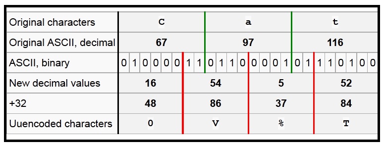
The encoding process is demonstrated by this table, which shows the derivation of the above encoding for "Cat".

So armed with my UU-encoding knowledge, I wrote a small program to carry out the conversion and explicitly show the process going on. Note the if statements at the bottom replacing any 0x00s with 0x60s. This is something I didn't discover on the first day and so I kept on getting slight discrepancies between my conversion and that provided by the online UU-Encoder I was using to check my output.
Type in 'Cat' and see for yourself that it agrees with the gods of Wikipedia.
Encoder.cpp
#include "mbed.h"

Serial pc(USBTX, USBRX);

int ch1, ch2, ch3;
int n1,n2,n3,n4;

int main() {
    while(1) {
        pc.baud(230400);
        n1 = 0; n2 = 0; n3 = 0; n4 = 0;

        ch1 = pc.getc();
        pc.printf("Raw bytes: %c", ch1);
        ch2 = pc.getc();
        pc.printf("%c", ch2);
        ch3 = pc.getc();
        pc.printf("%c\n\r", ch3);

        if ((ch1-128)>=0)   {ch1-=128;  n1+=32;}
        if ((ch1-64)>=0)    {ch1-=64;   n1+=16;}
        if ((ch1-32)>=0)    {ch1-=32;   n1+=8;}
        if ((ch1-16)>=0)    {ch1-=16;   n1+=4;}
        if ((ch1-8)>=0)     {ch1-=8;    n1+=2;}
        if ((ch1-4)>=0)     {ch1-=4;    n1+=1;}

        if ((ch1-2)>=0)     {ch1-=2;    n2+=32;}
        if ((ch1-1)>=0)     {ch1-=1;    n2+=16;}
        if ((ch2-128)>=0)   {ch2-=128;  n2+=8;}
        if ((ch2-64)>=0)    {ch2-=64;   n2+=4;}
        if ((ch2-32)>=0)    {ch2-=32;   n2+=2;}
        if ((ch2-16)>=0)    {ch2-=16;   n2+=1;}

        if ((ch2-8)>=0)     {ch2-=8;    n3+=32;}
        if ((ch2-4)>=0)     {ch2-=4;    n3+=16;}
        if ((ch2-2)>=0)     {ch2-=2;    n3+=8;}
        if ((ch2-1)>=0)     {ch2-=1;    n3+=4;}
        if ((ch3-128)>=0)   {ch3-=128;  n3+=2;}
        if ((ch3-64)>=0)    {ch3-=64;   n3+=1;}

        if ((ch3-32)>=0)    {ch3-=32;   n4+=32;}
        if ((ch3-16)>=0)    {ch3-=16;   n4+=16;}
        if ((ch3-8)>=0)     {ch3-=8;    n4+=8;}
        if ((ch3-4)>=0)     {ch3-=4;    n4+=4;}
        if ((ch3-2)>=0)     {ch3-=2;    n4+=2;}
        if ((ch3-1)>=0)     {ch3-=1;    n4+=1;}

        if (n1 == 0x00) n1=0x60;
        else n1+=0x20;
        if (n2 == 0x00) n2=0x60;
        else n2+=0x20;
        if (n3 == 0x00) n3=0x60;
        else n3+=0x20;
        if (n4 == 0x00) n4=0x60;
        else n4+=0x20;

        pc.printf("U-Encoded bytes: %c",n1);
        pc.printf("%c",n2);
        pc.printf("%c",n3);
        pc.printf("%c\n\n\r",n4);
    }
}
Maximising the Baud Rate
Initially, I could only communicate successfully with the mbed by sending commands to it at a 9600 baud rate. It turned out that this was as a result of the echo which the chip automatically has switched on when reset. To tackle this, I introduced a previously developed SerialBuffered class into my program to extend the FIFOs present on the mbed and switched off the echo as soon as handshaking had been achieved (sending the command 'A 0(+CR)'). After carrying out these adjustments, I could take it all the way up to 230400 baud, which is the limit described in the LPC1768 handbook. I tried higher, but apparently and annoyingly, they're right :(
The First Encoded Block
There is a small peculiarity in the process with which you carry out the encoding of the first block of data to be sent to the chip. This first block requires the 8th DWORD (a DWORD is a chunk of data consisting of 32 bits/4 bytes), to be the two's complement of the sum of the first 7 DWORDs. This is carried out by inverting all the bits in the 8th DWORD and adding 1 to it.
The code below is a slightly adapted version of the respective function in the final program at the end of this page. It carries out the summing, the two's complement creation (taking into account both little-endian and big-endian) and writes the altered first chunk of data to a temporary file called 'delete.bin'. Then this file can be opened, encoded and sent to the chip before reopening the original file and continuing from where it stopped before.
FirstEncode()
int SerialBuffered::FirstEncode() {
    long int precheck = 0;
    int a;
    for (a=0; a<9; a++) {
        ch1 = fgetc(f);  ch2 = fgetc(f);     ch3 = fgetc(f);
        sum[a*3]=ch1;    sum[(a*3)+1]=ch2;   sum[(a*3)+2]=ch3;
    }
    ch1 = fgetc(f);  fgetc(f);  fgetc(f);  fgetc(f);  fgetc(f);  //Ignores the 4 bytes which are to be overwritten
    sum[27] = ch1;

    for (a=0; a<7; a++) {
        sum1[a*4] = sum[a*4+3];
        sum1[a*4+1] = sum[a*4+2];
        sum1[a*4+2] = sum[a*4+1];
        sum1[a*4+3] = sum[a*4];
        precheck += (sum1[a*4]*0x1000000) + (sum1[a*4+1]*0x10000) + (sum1[a*4+2]*0x100) + sum1[a*4+3];
    }
    precheck = ~precheck+1;  //Takes the two's complement of the checksum
    sum[28] = precheck & 0xFF;
    sum[29] = (precheck >> 8) & 0xFF;
    sum[30] = (precheck >>16) & 0xFF;
    sum[31] = (precheck >>24) & 0xFF;
    sum[32] = fgetc(f);
    for (int a=33; a<46; a++) sum[a] = fgetc(f);
    f=fopen("/fs/delete.bin", "w");   //Opens a temporary file for writing to
    fwrite (sum, 1, sizeof(sum), f);  //Writes the checksum-added and encoded bytes
    fclose(f);
    return 0;
}
Success!


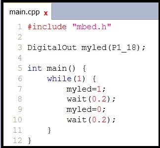
Undeniable blinky proof that it works. (Zipped video clip of an LED connected to P1.18 flashing)
Bootloader Program
In order to use the program, compile the program you want to bootload onto another chip and drop it into the mbed's filesystem flash (in place of the standard pin names (PinName7, LED1 etc.), you can access any of the LPCs pins in the format shown in the compiler image above of P(Bank number)_(Pin number), for example P1_18.
Then open up the program given below, change the name of the file you wish to load in the main.cpp, compile it, and reset the mbed to flash it to the chip. Simple!
If anything needs explaining, then feel free to comment below and I'll try to get round to answering any queries that crop up.
