You are viewing an older revision! See the latest version
lpc bootloader
Once you have created a prototype of your product, you may want to be able to use the developed code on a target MCU (NXP LPC1xxx) in situ in your end-application board.

This page documents the development of a LPC1xxx bootloader program which makes the following process possible:
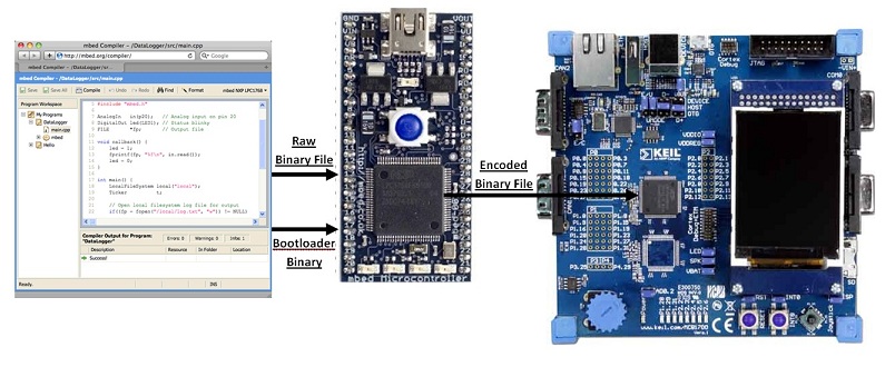
- The binary file to flash the target MCU with is placed on the mbed's local filesystem.
- The bootloader program is loaded onto the mbed's local filesystem and run, loading an encoded version of the binary file onto the LPC1xxx chip.
Chris Styles already experimented with bootloading NXP chips in Prototype to Hardware. This carries out the desired process, but makes use of the Flash Magic flash utility. This requires the user to convert the binary file into hex and then put it through the flash utility. Hence, the process could be streamlined by allowing binary files to be directly loaded, which is now possible using this bootloader program.
The Task Ahead
I started off by leafing through the UM10360 datasheet, which contains the information on the current evolution of the mbed (LPC1768). As always, you should start by reading from the very beginning (of page 615). This chapter looks at the flash memory interface and documents the In-System Programming (ISP) which is the serial communication path used for this bootloader. From reading through it, you gauge what is required:
Hardware (for the LPC1768):
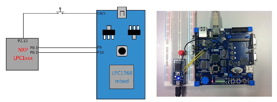
- In order to start the chip up in ISP bootloader mode, you need to breakout P2.10 and pull it low when resetting the board, for at least three milliseconds (possibly with a push button).
- Connect P9 of the mbed to P0.2 of the LPC chip
- Connect P10 of the mbed to P0.3 of the LPC chip

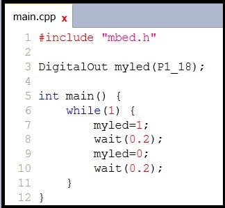
I used a Keil MCB1760 evaluation board as a 'breakout board' for my chip to bootload to (LPC1768 as well). This allowed easy access to the pins I required access to without any pixie soldering and conveniently gives me LEDs to flash to let me know when my work has been done. Well, that was easy. The MCB1760 had the ISP entry pin, P2.10, already pulled high, so I was lazy and just put in place a pushbutton connected to ground in order to pull the pin low when ISP bootloader mode entry was required. Now onto the software...
Software:
- Get the mbed to access the desired file on the local filesystem.
- Synchronise the mbed with the chip, by doing the handshaking (in ASCII strings).
- Prepare and erase the entire flash memory.
- Override the 8th DWORD with the two's complement of sum of the first 7 DWORDs. This is the chip's first checksum (it sums the first 8 DWORDs continues if the result is zero).
- Convert the file line-by-line into the UU-encoded format (discussed later) ending with a line feed and/or carriage return character).
- Send the checksum of the sum of the raw bytes sent in the last block (sent after a 20 line block).
- Write a 1KB block of the binary file to the RAM in the above process.
- Prepare the flash memory for writing to and copy the RAM block to the suitable location in the flash.
I developed the code on the mbed's online compiler and debugged the serial communications using a USBee SX with its accompanying USBee Suite software and drivers.
(If trying to replicate the debugging setup, ensure you set up an asynchronous (8-N-1) connection decoding into ASCII unless you're fluent in binary.)
!!MIDDLE CHUNK BEING WRITTEN PRESENTLY!!
Success!


