You are viewing an older revision! See the latest version
CatsRjERKS
Cats R Jerks
Description
In this project, a rather unfriendly cat is simulated. An LV-MAXSonar-EZ0 will be the ‘cat’ in this project, reading how close you are getting to it. Using a Speaker and uLCD Display with unique SD cards for each, the state of the cat is displayed.
Components and Libraries
This section is for information about different reusable building blocks; primarily components and the libraries, code and information to make use of them. For more about Libraries, see Working with Libraries.
What You Will Need
- uLCD-144-G2
- SD Card Reader from Sparkfun: https://www.sparkfun.com/products/544
- LV-MAXSonar-EZ0 from MaxBotix
- Speaker – PCB Mount from Sparkfun
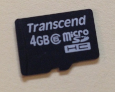
- 2 SD Card
- 1k Resistor
- 2N3904 Transistor
uLCD Display
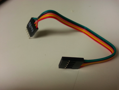
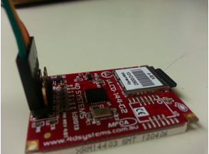
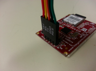
The uLCD Display has two rows of pins. Use a cable to hook up the breadboard to the row of pins closer to the edge of the display board. +5 V will be the leftmost pin if looking at the board with the label upright.

SD Card for uLCD Display
The SD Card being used is going into the SD slot mounted to the uLCD. This, however, requires some editing upon the SD card. Using the 4D Workshop IDE from this site http://www.4dsystems.com.au/product/10/120/Development/4D_Workshop_4_IDE/
take an SD card and clear its partitions using the IDE’s RMPET tool. Using the same tool, partition the SD card into two sections: 50% FAT and 50% unformatted. Due to the nature of the uLCD display, the JPG files for the Cat images must be stored in the unformatted half of the SD card. After having re-formatted the SD card, resize the JPG files of the Cat, to be 128 by 128 pixels, as these are the dimensions of the uLCD screen. Using instructions from this link with the Graphics Composer tool of the IDE
mount the three images to the SD card. In this project, the files being used are NiceCat.jpg, NervousCat.jpg, and AngryCat.jpg. After having stored the images onto the SD card, the Graphics Composer tool will output a .GC file. Here you will be able to find the sectors at which the files are located in order to access them in the code.
The Speaker
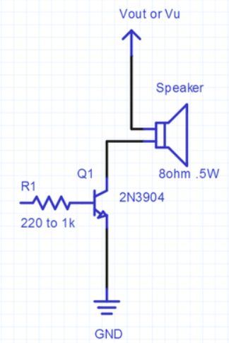
The Speaker-PCB mount has the Positive pin hooked up to VOUT of the MBED. The Negative pin is tied to the collector pin of a 2N3904 transistor. The base of the transistor is tied to a 1k resistor that is in turn connected to Pin 18 of the MBED. The emitter of the transistor is tied to GND as shown in the image below:
