Port from Avnet's Internet Of Things full WiGo demo: SmartConfig - WebServer - Exosite - Android sensor Fusion App
Dependencies: mbed CC3000_Hostdriver TEMT6200 TSI Wi-Go_eCompass_Lib_V3 WiGo_BattCharger
Fork of CC3000_Simple_Socket by
Information
This demo uses the old HostDriver.
A newer release using the mbed socket compatible API HostDriver is available at Wi-Go_IOT_Demo_MKII.
Wi-Go Reference Design Overview
For additional information on Wi-Go, please visit http://www.em.avnet.com/wi-go
For additional information on Freescale eCompass, please visit
http://www.freescale.com/webapp/sps/site/prod_summary.jsp?code=E-Compass
Ported from Avnet's Wi-Go KEIL code.
Special thanks to Jim Carver from Avnet for providing the Wi-Go board and for his assistance.
Multiple Wi-Fi applications are provided within the latest version of Wi-Go software:
- SmartConfig App for auto-setup of Wi-Go network parameters.
- WebServer display of live sensor data.
- Exosite portal sensor data feed by Wi-Go.
- Freescale's Sensor Fusion App data feed by Wi-Go.
Wi-Go is intended for "untethered" portable operation (using it's high-capacity Lithium-Polymer battery). The serial terminal text interface is only required for initial setup, thereafter selection of an application from those available is via finger position on the Touch Slider during the initial 6 second startup period.
Running the Wi-Go Demo Suite
Warning
- We need a large amount of free RAM for the eCompass library:
Before compiling the code, check ifCC3000_MAXIMAL_RX_SIZEis set to(511 + 1)incc3000_common.h.
- The on-board Firmware must be updated to mbed enable a Wi-Go system. Goto the Component page to get the FirmwareUpdate tool (scroll down to the FirmwareUpdate topic).
MAG3110 sensor and eCompass Calibration!
As with the other sensor applications, the eCompass function requires quality calibration data to achieve best accuracy.
For the first 15 seconds after power-up it is recommended that "Figure 8" movements with Wi-Go be done in a smooth, repetitive pattern. Don't touch the slider pad during calibration.
Startup
The RGB LED blinks in a GREEN-ORANGE sequence to inform the user the module is waiting for input.
The RGB LED color designates which of the following Apps to launch.
| RGB LED Color | Application to Launch |
| Purple | SmartConfig |
| Blue | WebServer |
| Red | Exosite Data Client |
| Green | Android Server |
Swipe your index finger across the slider pad, the RGB LED color will change at approximately 25% intervals.
Removing your finger latches the last color displayed. After about 3 seconds, the selected app will start.
Another app can be selected when the slider pad is touched again within the 3 seconds timeout.
After launch of Exosite or Android Server Apps, the eCompass function then controls the RGB LED.
(not in WebServer mode where RGB LEDs are manually controlled by the User).
| RGB LED Color | Direction Indication |
| Blue | Near to North |
| Green | North |
| Red | East / West |
| Purple | South |
__Note!__ The D1, D2 and D3 User LEDs on Wi-Go adhere to the following convention for the different Apps
| User LED# | Description of function controlling the LED |
| D1 | is the board heartbeat, derived from the timer interrupt |
| D2 | indicates network activity as follows: Web Server Wi-Go webpage is being served. Exosite Client Wi-Go is sending data. Android App Wi-Go is sending data |
| D3 | WLAN Network is Connected |
Detail of Wi-Go Applications
App #1: SmartConfig
See TI's pages on how to use the SmartConfig tool:
- Preferred method : Configuration using the SmartConfig tool
- SmartConfig download: Smart Config and Home Automation
- iOS app : available at Apple app store.
- Android app : download and install the Android SmartConfig Application on a PC.
This file contains the source code as well as the compiled APK file.
The APK file is stored inti\CC3000AndroidApp\SmartConfigCC3X\bin.
- iOS app : available at Apple app store.
App #2: WebServer display of live sensor data
__Note!__
When using the WebServer for the first time on a Wi-Fi network you will need to determine the IP address that's assigned to Wi-Go by the DHCP Server. To do this, it is recommended you use one of the following two methods:
- While Wi-Go is initially tethered to a laptop via USB, launch of the WebServer Application and note the IP address that is reported on the terminal screen immediately after selection of this App.
- Alternatively, use a 3rd party LAN SCAN type tool to view Wi-Go's IP address.
eg.FING, - available for free download from Google Play or iTunes App Stores…
Wi-Go's WebServer Application is selected as follows:
- Press RESET, followed by the
eCompass Calibration(mentioned at the top of this page).
Then use index finger on slider to select the WebServer App (RGB LED = BLUE).
At end of the 3 second selection period the WebServer App shall launch.
- If you are tethered to a laptop and have a terminal open the Wi-Fi network connection confirmation will be seen, eg.
'*** Wi-Go board DHCP assigned IP Address = 192.168.43.102
- Once you have noted Wi-Go's reported IP address, the USB cable may be disconnected and Wi-Go then used as intended, running on it's own battery power.
- Use an Internet Browser on SmartPhone/Tablet/Laptop (connected to same Hot-Spot/Wireless Router subnet), to now connect to the noted Wi-Go IP address and view the WebServer output:
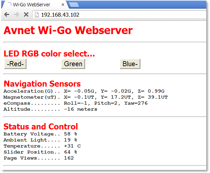
- the Webserver sensor data is auto-updated every 2 seconds a manual refresh (F5 on laptop).
- In the event of an error, press refresh to regenerate the screen.
- Use the mouse (or touch-screen) to exercise the RGB LED output.
App #3: Exosite Data Client
Wi-Go's sensor data gets transmitted via Wi-Fi to a cloud-based Exosite portal where the sensor measurements are displayed graphically on a "dashboard". Users can create unique customized dashboards using drag and drop GUI widgets from the library provided on the Exosite website.
__Note!__ For the Exosite application a "live" connection to the Internet is required !!!
- Press RESET, followed by the
eCompass Calibration(mentioned at the top of this page).
Then use index finger on slider to select the Exosite Client App (RGB LED = RED) - On launching this App, note Wi-Go's MAC address displayed on your terminal
(if not running a terminal use FING or other WLAN Scan tool to determine Wi-Go's MAC address)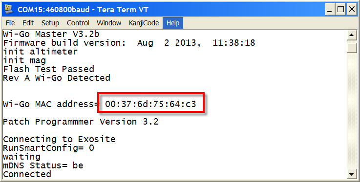
- Using your computer's internet browser, go to avnet.exosite.com and sign-up for a free
Avnet TrialExosite Account: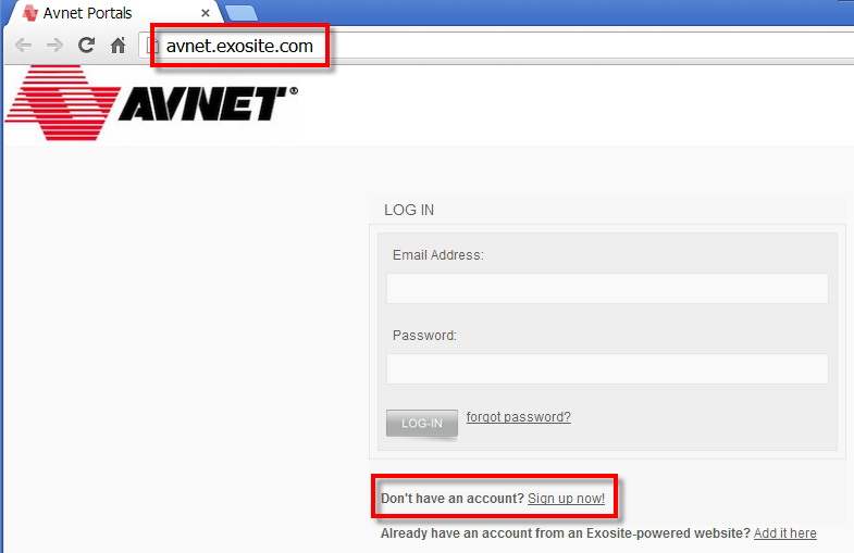
- On the next screen, click on the Sign-Up Now button in the displayed
Avnet Trialaccount option. - Complete the Account Info and Contact Info then click on Create Account (make sure to use a valid email address!).
- Check for new incoming email from avnet.exosite.com to the address you provided and click on the link in this email to activate your new Exosite account.
- Once activated, login using the email address and password that you chose in your registration.
Your Exosite Portal and Dashboard should now display. The first time you log-in to your new account, the default Home dashboard will be displayed, pre-configured with two widgets. On the left is the Welcome widget for tips and information. On the right is the Device List widget.
Dashboards are configurable, so at any time this default dashboard can be changed, widgets deleted and added (Clicking the upside-down triangle icon in a widget's Title bar will allow you to edit it). - Before going further with the Dashboard, you need to connect your Wi-Go device to your Exosite account. Do this by going to the left sidebar and selecting Devices followed by selecting the +Add Device link (on right of screen).

- In the Setup screens that follow, enter the following
| Select a supported device | Wi-Go |
| Enter device MAC Address | nn:nn:nn:nn:nn:nn [your Wi-Go's MAC address including colons] |
| Enter device Name | [choose a descriptive name] |
| Enter device Location | [description of your location] |
- Once completed, under Devices the name chosen for the added Wi-Go device should now be listed.
- Click on this new Wi-Go device to examine (and edit if necessary) it's Device Information screen.
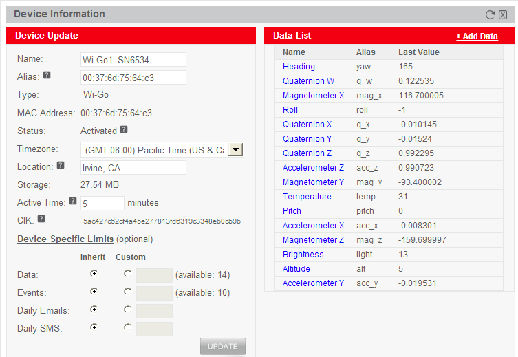
- Click the CLOSE button to exit the Device Information screen.
- On your Wi-Go kit now press RESET, followed by the
eCompass Calibration(mentioned at the top of this page)
and again select the Exosite Client App (RGB LED = RED) using your index finger. - Refresh your browser (press F5) a couple've times until the Active indicator changes to On (Green).

- From the left sidebar click on Home and click on the recently named Wi-Go device which is located under the Device List.
This will bring-up a default dashboard display similar to what's shown below.
(Dashboards are typically accessed via the Dashboards menu entry). Check the dashboard is updating with live data by moving your Wi-Go Kit through different orientations.

- To create a custom dashboard, select Dashboards from the sidebar menu, followed by +Add Dashboard (on right side of Your Dashboards title bar). After completion of the initial configuration screen you will then be able to add Widgets to display the various Wi-Go data sources as well as pictures and text to support your application.
- More guidance on the creation, editing and sharing of custom dashboards is available under the Exosite support pages
App #4: Android Sensor Fusion App
- Press RESET, followed by the
eCompass Calibration(mentioned at the top of this page)
, then use index finger on slider to select the Android App (RGB LED = GREEN)
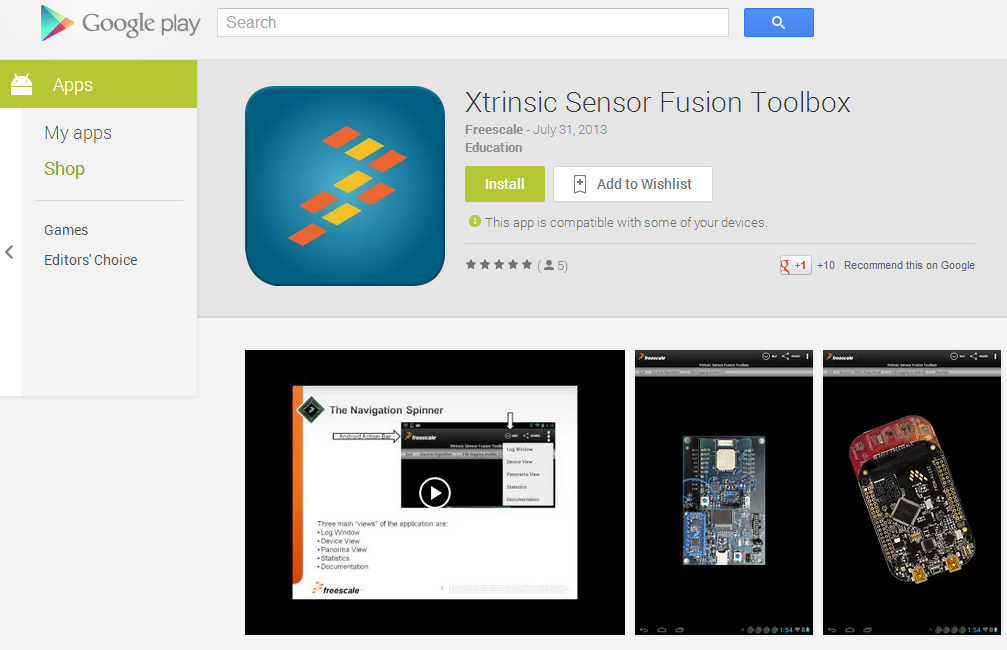
- Freescale's ''Xtrinsic Sensor Fusion Toolbox'" will run on Android 3.0 or above phone or tablet. Free to download from Google Play, type Sensor fusion in the search box to find it.
freescale.sensors.sfusion
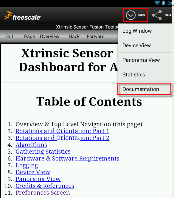
- The Freescale App is well documented. To access the built-in documentation, press the NAV button at top of screen followed by Documentation from the scroll-down menu:
- Freescale's sensors site provides additional resources such as this overview:
free-android-app-teaches-sensor-fusion-basics
- Go to the Options Menu and select Preferences…
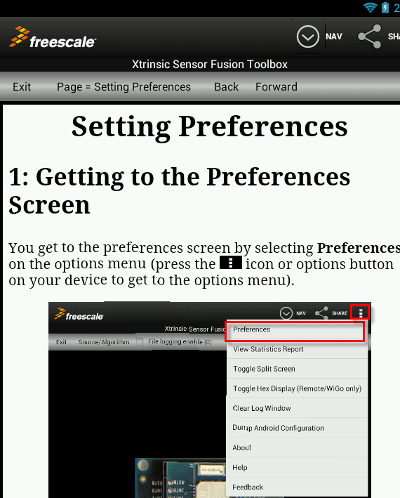
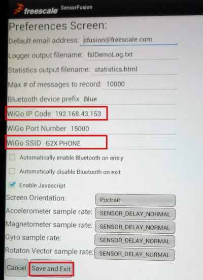
- The following items need to be taken care of:
| Enter WiGo's IP address |
| Enter the SSID (of the Hot-Spot or Wireless Access Point used by Wi-Go) |
- Press Save and Exit!
- Exit the Application completely then re-launch the Sensor Fusion Application.
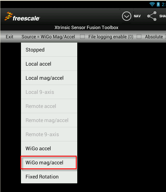
- Select the ''Source/Algorithm'" menu and change the data source to Wi-Go mag/accel
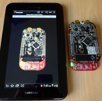
- The Android App should now be displaying a 3-D image of Wi-Go that you can rotate and flip-over by moving the Wi-Go board accordingly…
- Use NAV > Device View to display if this view does not come-up by default.
- A Serial Terminal connection is not necessary but if you happen to have one open you should see the following messages as Wi-Go connects to the Android App:
"Server waiting for connection" followed by
"connected, transmit buffer size= 96", and then
"input = 0123456789"
at which time Wi-Go starts streaming data to the Android App.
Diff: Drivers/I2C_busreset/I2C_busreset.cpp
- Revision:
- 15:cc204c19f888
--- /dev/null	Thu Jan 01 00:00:00 1970 +0000
+++ b/Drivers/I2C_busreset/I2C_busreset.cpp	Sun Dec 01 19:32:20 2013 +0000
@@ -0,0 +1,58 @@
+/**************************************************************************************************
+ *****                                                                                        *****
+ *****  Name: KL25Z I2C_busreset.cpp                                                          *****
+ *****  Date: 24/11/2013                                                                      *****
+ *****  Auth: Frank Vannieuwkerke                                                             *****
+ *****  Func: library for unblocking I2C bus on KL25Z board                                   *****
+ *****  Info: MPL3115A2-AN4481                                                                *****
+ **************************************************************************************************/
+
+#include "I2C_busreset.h"
+
+void I2C_busreset(void)
+{
+    I2C0->C1 &= 0x7f;                 // Disable I2C0 bus
+    I2C1->C1 &= 0x7f;                 // Disable I2C1 bus
+    PORTE->PCR[1] = PORT_PCR_MUX(1);  // PTE1 Alt1 (pin)
+    PORTE->PCR[0] = PORT_PCR_MUX(1);  // PTE0 Alt1 (pin)
+    PORTE->PCR[24] = PORT_PCR_MUX(1); // PTE24 Alt1 (pin)
+    PORTE->PCR[25] = PORT_PCR_MUX(1); // PTE25 Alt1 (pin)
+    if((PTE->PDIR & 0x3) != 3)        // When PTE0 / PTE1 are not 1 : I2C1 bus lock-up
+    {
+        PTE->PDDR |= 0x2;             // Set PTE1 as a GPIO output so we can bit bang it
+        PTE->PDOR |= 0x2;             // Set PTE1 (SCL) pin high;
+        wait_ms(1);
+        while(!(PTE->PDIR & 0x1))     // bit bang SCL until the offending device releases the bus
+        {
+            PTE->PDOR &= 0xfffffffd;  // Set PTE1 (SCL) pin low;
+            wait_ms(1);
+            PTE->PDOR |= 0x2;         // Set PTE1 (SCL) pin high;
+            wait_ms(1);
+        }
+    }
+    if((PTE->PDIR & 0x03000000) != 0x03000000)  // When PTE24 / PTE25 are not 1 : I2C0 bus lock-up
+    {
+        PTE->PDDR |= 0x01000000;      // Set PTE24 as a GPIO output so we can bit bang it
+        PTE->PDOR |= 0x01000000;      // Set PTE24 (SCL) pin high;
+        wait_ms(1);
+        while(!(PTE->PDIR & 0x1))     // bit bang SCL until the offending device releases the bus
+        {
+            PTE->PDOR &= 0xfeffffff;  // Set PTE24 (SCL) pin low;
+            wait_ms(1);
+            PTE->PDOR |= 0x01000000;  // Set PTE24 (SCL) pin high;
+            wait_ms(1);
+        }
+    }
+    // Reinstate I2C bus pins
+    PORTE->PCR[1] = PORT_PCR_MUX(6);  // PTE1 Alt6 (SCL)
+    PORTE->PCR[0] = PORT_PCR_MUX(6);  // PTE0 Alt6 (SDA)
+    PORTE->PCR[24] = PORT_PCR_MUX(5); // PTE24 Alt6 (SCL)
+    PORTE->PCR[25] = PORT_PCR_MUX(5); // PTE25 Alt6 (SDA)
+    I2C0->C1 |= 0x80;                 // Enable I2C0 bus
+    I2C1->C1 |= 0x80;                 // Enable I2C1 bus
+}
+
+
+
+
+
