Lets LED blinky on mbed LPC1114FN28
If you can't read English, here is the documentation in Japanese.
http://mag.switch-science.com/2014/06/06/led_blinky_at_mbed_lpc1114fn28/
Choose platform
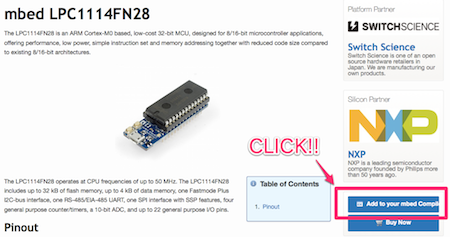
Go to the platform page.
Click “Add to your mbed compiler”.
Write a program & Make a circuit
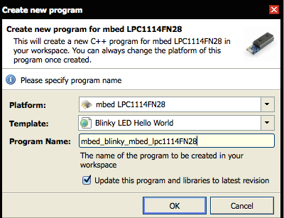
Click "New" button and crate a project on online compiler.
Choose platform the mbed LPC1114FN28.
Click "OK" button.
Compile and Download this program(default).
#include "mbed.h"

DigitalOut myled(LED1);

int main() {
    while(1) {
        myled = 1;
        wait(0.2);
        myled = 0;

        wait(0.2);
    }
}
The mbed LPC1114FN28 don’t have LED for blinking.We need to connect LED with it.
Let’s refer this pin-out.
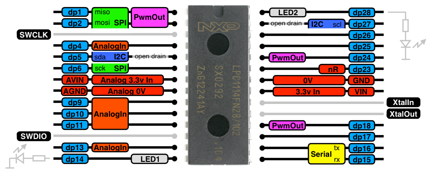
Make the circuit following.
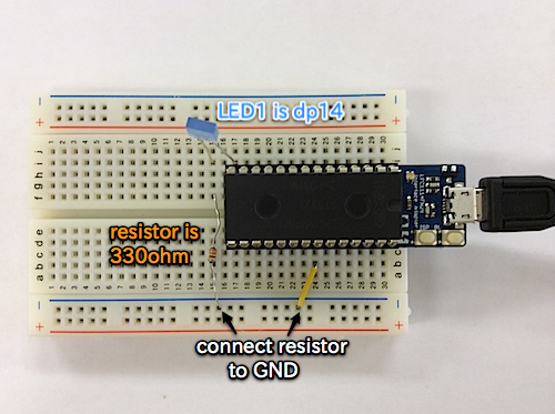
Don’t forget connecting resistor between LED and your mbed.
Your mbed is unrecognized by PC after Drug and Drop the binary file.But it is immediately recognized again.
Hit the BL button,then LED is blinking!!
After write the program,You won’t be able to find it in MBED drive.But it’s normal behavior.
Additional information
The mbed LPC1114FN28 includes LED indicator and two buttons.
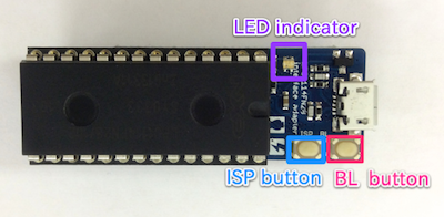
LED color meaning :
- Red:MBED volume
- Green:CMSIS-DAP
- Blue:USB-UART bridge
ISP button is used just rewriting firmware.
BL button is used just resetting.
You should update latest firmware before you use your mbed.
Please refer to this instruction.
https://mbed.org/teams/Switch-Science/wiki/Firmware-LPC1114FN28
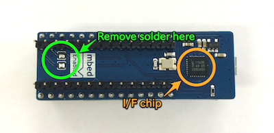
The firmware is used I/F chip on the substrate backside.This is LPC 11U35 support following.
- Writing by drug & drop
- Connecting Serial communication
- The CMSIS-DAP debug interface
If you use another UART devices,you should remove solder connecting TX,RX of I/F chip to RX(dp15), TX(dp16) of LPC1114FN28.
