Renesas
Renesas Electronics Corporation (TSE: 6723), the world's number one supplier of microcontrollers, is a premier supplier of advanced semiconductor solutions including microcontrollers, SoC solutions and a broad range of analog and power devices.
You are viewing an older revision! See the latest version
GR PEACH rev_B version information
Platform information
See Platform.
Jumper settings
| JP# | description | default |
|---|---|---|
| JP1 | RST button directly connect to RZ/A1H | open |
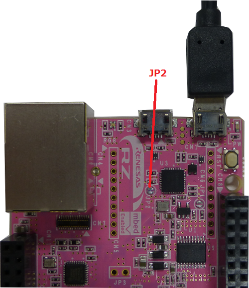
| JP2 | Update mbed CMSIS-DAP firmware | open |
| JP3 | VBUS supply to USB Host/Function | open |
| JP4 | short diode not to drop voltage | open |
| JP5 | short diode not to drop voltage | open |
| JP6 | short diode not to drop voltage | open |
Supported function map
mbed Libraries
Note: "Done" means that you can import it on the mbed on-line compiler.
| Function | Support | merged to mbed-src | registered to mbed library | Note |
|---|---|---|---|---|
| AnalogIn | ✓ | Done | Done | - |
| AnalogOut | - | - | - | RZ-A1H does not have this function. |
| DigitalIn | ✓ | Done | Done | Pull up and Pull down settings aren't supported because RZ/A1H doesn't have pull up/down for pins(signals). [Affected APIs] DigitalIn(PinName pin) DigitalIn(PinName pin, PinMode mode) void mode(PinMode pull) |
| DigitalOut | ✓ | Done | Done | Pull up and Pull down settings aren't supported because RZ/A1H doesn't have pull up/down for pins(signals). [Affected APIs] DigitalOut(PinName pin) DigitalOut(PinName pin, int value) |
| DigitalInOut | ✓ | Done | Done | Pull up and Pull down settings aren't supported because RZ/A1H doesn't have pull up/down for pins(signals). [Affected APIs] DigitalInOut(PinName pin) DigitalInOut(PinName pin, PinDirection direction, PinMode mode, int value) void mode(PinMode pull) |
| BusIn | ✓ | Done | Done | Pull up and Pull down settings aren't supported because RZ/A1H doesn't have pull up/down for pins(signals). [Affected APIs] BusIn(...) void mode(PinMode pull) |
| BusOut | ✓ | Done | Done | Pull up and Pull down settings aren't supported because RZ/A1H doesn't have pull up/down for pins(signals). [Affected APIs] BusOut(...) |
| BusInOut | ✓ | Done | Done | Pull up and Pull down settings aren't supported because RZ/A1H doesn't have pull up/down for pins(signals). [Affected APIs] BusInOut(...) void mode(PinMode pull) |
| PortIn | - | - | - | Please use BusIn instead |
| PortOut | - | - | - | Please use BusOut instead |
| PortInOut | - | - | - | Please use BusInOut instead |
| PwmOut | ✓ | Done | Done | The maximum period is 491us When you set a number greater than 491us, 491us is set. [Affected APIs] void period(float seconds) :max:4.91e-4 void period_ms(int ms) :ms<=0:1us , ms>=1:491us void period_us(int us) :max:491 The combination of the following pins are exclusively use. ・P4_6 or P4_7 ・P8_8 or P8_9 ・P8_10 or P8_11 ・P8_12 or P8_13 ・P8_14 or P8_15 [Affected APIs] PwmOut(PinName pin) The period of the following pins can be set to the same value. ・channel 1: P8_8,P8_9,P8_10,P8_11,P8_12,P8_13,P8_14,P8_15 ・channel 2: P10_0,P3_2,P4_4,P4_6,P4_7 [Affected APIs] PwmOut(PinName pin) void period(float seconds) void period_ms(int ms) void period_us(int us) |
| InterruptIn | ✓ | Done | Done | Pull up and Pull down settings aren't supported because RZ/A1H doesn't have pull up/down for pins(signals). [Affected APIs] void mode(PinMode pull) The combination of the following pins are exclusively use. ・IRQ0:P1_0,P2_14,P4_8,P5_8,P6_8,P7_9,P8_2 or P9_1 ・IRQ1:P1_1,P2_15,P4_9,P6_9,P7_8,P8_3 or P11_15 ・IRQ2:P1_2,P1_8,P3_0,P4_10,P5_9,P6_3,P6_10 or P7_10 ・IRQ3:P1_3,P1_9,P4_11,P6_4,P6_11,P7_11 or P11_12 ・IRQ4:P1_4,P1_10,P3_3,P4_12,P6_1,P6_12 or P7_12 ・IRQ5:P1_5,P1_11,P2_0,P4_13,P6_0,P6_13,P7_13 or P8_7 ・IRQ6:P1_6,P2_12,P3_1,P3_9,P4_14,P5_6,P6_14 or P7_14 ・IRQ7:P1_7,P2_13,P4_15,P6_2 or P6_15 [Affected APIs] InterruptIn(PinName pin) |
| Timer | ✓ | Done | Done | - |
| TimeOut | ✓ | Done | Done | - |
| Ticker | ✓ | Done | Done | - |
| wait | ✓ | Done | Done | - |
| time | ✓ | Done | Done | - |
| Serial | ✓ | Done | Done | 5-bits format and 6-bits format are not supported. Because RZ/A1H does not support such a function. In the flow control, flow types using only either of CTS or RTS is not supported. Because RZ/A1H does not support. |
| SPI | ✓ | Done | Done | - |
| SPISlave | ✓ | Done | Done | - |
| I2C | ✓ | Done | Done | - |
| I2CSlave | ✓ | Done | Done | - |
| CAN | ✓ | end of 2015/Apr. | end of 2015/May. | - |
mbed official Libraries
Note: "Available" means that you can import it on the mbed on-line compiler.
| Function | Support | Availability | Note |
|---|---|---|---|
| mbed RTOS | ✓ | Available | - |
| LocalFileSystem | - | - | No plan to support. |
| SDFileSystem | ✓ | Available | - |
| USBDevice | ✓ | Available | - |
| USBHost | ✓ | Available | - |
| Ethernet | ✓ | Available | - |
| EthernetInterface | ✓ | Available | - |
Other Libraries
Note: "Available" means that you can import it on the mbed on-line compiler.
| Function | Support | Availability | Note |
|---|---|---|---|
| CMSIS-DSP(NEON) | ✓ | end of 2015/May | - |
Getting Started
Preparation
Install the USB serial communication driver
For Windows(R) user:
- Connect GR-PEACH and PC.
- After the mount GR-PEACH as "MBED" volume label, install this driver.
Add compiler for GR-PEACH
- The root folder of GR-PEACH mass storage drive includes "mbed.htm" .
- This file jumps to the site of GR-PEACH when double clicked.
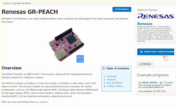
- You can use mbed compiler for GR-PEACH after click at "Add to your compiler" button.

Build and Run
How to import, compile, and run.
- Then launch the development environment from Compiler button.
- Import programs you need.
- Click "Import Program" button.
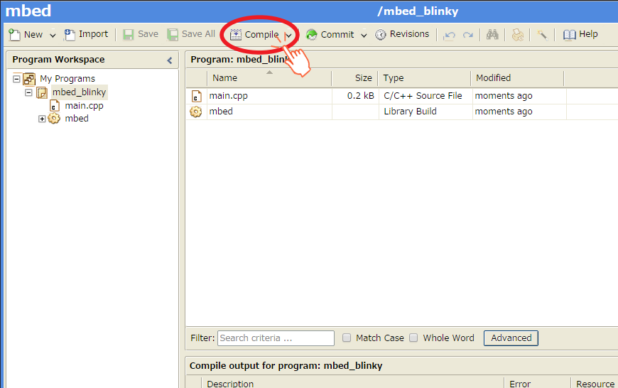
- Create binary file to click the "Compile" button.

- When compile is finished, binary file is downloaded using browser function.
Copy this file to mbed drive.
For Window user: drag and drop.
For Mac user : Refer here - When GR-PEACH's reset button is pushed or reconnect USB cable, the program runs.
Let's blink LED
- Import mbed_blinky.
Blink LED smoothly
Edit main.cpp of mbed_blinky.
LED PWM
#include "mbed.h"

PwmOut led(LED_RED);

int main() {
    float crt = 1.0, delta = 0.04;

    led.period_ms(2); // 500Hz
    while (true) {
        led.write(crt);
        wait_ms(50);
        crt = crt + delta;
        if (crt > 1.0) {
            crt = 1.0;
            delta = -delta;
        }
        else if (crt < 0) {
            crt = 0;
            delta = -delta;
        }
    }
}
Use A/D converter
A/D conversion uses A0 and A1 of Arduino pinout
#include "mbed.h"

DigitalOut myled(LED1);
AnalogIn   ain0(A0);
AnalogIn   ain1(A1);

int main() {
    myled = 1;
    while(1) {
        myled = !myled;
        printf("ain0 = %8.3f, ain1 = %8.3f\n", ain0.read(), ain1.read());
        wait(1);
    }
}
Use Serial Peripheral Interface(SPI)
SPI communication uses from D10 to D13 of Arduino pinout
#include "mbed.h"
SPI spi(D11, D12, D13);   // mosi, miso, sclk
DigitalOut cs(D10);

int main() {
    int data = 0;
    int res = 0;

    for(int i = 0; i < 30; i++) {

        cs = 0;
        res = spi.write(data++);
        cs = 1;

        wait_ms(0.001);
    }
}
Use I2C
I2C communication uses SDA and SCL on Arduino pinout
#include "mbed.h"

#define SIZE (10)
#define ADDR (0x90)

I2C i2c(I2C_SDA, I2C_SCL);

int main() {
    char buf[] = {1, 2, 3, 4, 5, 6, 7, 8, 9, 10};
    char res[SIZE];

    i2c.write(ADDR, buf, SIZE);
    i2c.read(ADDR, res, SIZE);
}
Use microSD
To use micro SD, you need to add SD File System.
- Select the root directory of this project, then click the "Import this library" on the right of SD file system.
- During importing, the dialog appears.
**DO NOT CHECK the "Update all libraries to the latest version".**
microSD control using SPI interface.
#include "mbed.h"
#include "SDFileSystem.h"

SDFileSystem sd(P8_5, P8_6, P8_3, P8_4, "sd");

namespace {
const char *sd_file_path = "/sd/out.txt";
const int DATA_SIZE = 256;
}

int main()
{
    uint8_t data_written[DATA_SIZE] = { 0 };
    bool result = true;

    // Fill data_written buffer with random data
    // Write these data into the file
    {
        FILE *f = fopen(sd_file_path, "w");

        printf("SD: Writing ... ");
        for (int i = 0; i < DATA_SIZE; i++) {
            data_written[i] = rand() % 0XFF;
            fprintf(f, "%c", data_written[i]);
        }

        printf("[OK]\r\n");
        fclose(f);
    }

    // Read back the data from the file and store them in data_read
    {
        FILE *f = fopen(sd_file_path, "r");
        printf("SD: Reading data ... ");
        for (int i = 0; i < DATA_SIZE; i++) {
            uint8_t data = fgetc(f);
            if (data != data_written[i]) {
                result = false;
                break;
            }
        }
        printf("[%s]\r\n", result ? "OK" : "FAIL");
        fclose(f);
    }
}
Use Ethernet
sample code of ehternet interface
#include "mbed.h"
#include "EthernetInterface.h"

struct s_ip_address
{
    int ip_1;
    int ip_2;
    int ip_3;
    int ip_4;
};

int main() {
    char buffer[256] = {0};
    s_ip_address ip_addr = {0, 0, 0, 0};
    int port = 0;

    printf("TCPCllient waiting for server IP and port...\r\n");

    EthernetInterface eth;
    eth.init("192.168.100.2", "255.255.255.0", "192.167.101.3");
    eth.connect();

    printf("TCPClient IP Address is %s\r\n", eth.getIPAddress());
    sprintf(buffer, "%d.%d.%d.%d", ip_addr.ip_1, ip_addr.ip_2, ip_addr.ip_3, ip_addr.ip_4);

    TCPSocketConnection socket;
    while (socket.connect(buffer, port) < 0) {
        printf("TCPCllient unable to connect to %s:%d\r\n", buffer, port);
        wait(1);
    }

    while ( true ) {
        wait(1);
    }

    socket.close();
    eth.disconnect();
    return 0;
}

// set mac address
void mbed_mac_address(char *mac) {
    mac[0] = 0x00;
    mac[1] = 0x02;
    mac[2] = 0xF7;
    mac[3] = 0xF0;
    mac[4] = 0x00;
    mac[5] = 0x00;
}
To use Ethernet, you need to add "mbed-RTOS" and "EthernetInterface".
- Click the "Import" button.
- Select "mbed-rtos" and "EthernetInterface" from library tag, then click "Import!".
- And compile this program and download on the GR-PEACH.
- Set the IP address of your PC to "192.168.100.100".
- Connect between GR-PEACH and your PC using LAN cable.
- Reset GR-PEACH.
Then GR-PEACH outputs follows message.
TCPCllient waiting for server IP and port...
TCPClient IP Address is 192.168.100.2
8. Run the ping command from your PC to GR-PEACH.
PING 192.168.100.2
CMSIS-DAP firmware Update
0. Preparation
Download a firmware from the following URI.
- Latest version
grpeach_8mb_20150318.bin- support drag-and-drop writing on OS X Yosemite.
- Current version
grpeach_8mb_20141217.bin- This firmware is written in the current GR-PEACH rev.C.
- Connect GR-PEACH to PC
Please make a short-circuit at JP2 when you connect USB cable between GR-PEACH and PC.

- After the connection, it will appear as a disk called "CRP DISABLED".
If "mbed" appears, the short-circuit of JP2 doesn't succeed.
In this case, please re-try the previous item.
When GR-PEACH connected as "CRP DISABLED", JP2 can be opened during firmware updating. - Open the "CRP DISABLED" disk folder and delete the Firmware.bin. (Please check the following Note.)
- Copy the downloaded file to this drive. (Please check the following Note.)
Note
For Mac user: please check the following URL instead of step 3 and 4.
: Refer here
5. Disconnect between GR-PEACH and PC after copy is finished.
6. Reconnect GR-PEACH and PC.
7. When USB disk appears as "mbed", firmware update is finished.
defects (問題)
| No | module | description | status | preliminary | release date |
|---|---|---|---|---|---|
| 0 | - | - | - | - | - |
issues (課題)
| No | module | description | status | release date |
|---|---|---|---|---|
| 1 | CAN | support CAN library | under development | end of 2015/Apr |
| 2 | USBHost | support USBHost library (isochronous) | under development | end of 2015/Mar |
| 3 | mbed RTOS | change the method of obtaining stack as same as Cortex-M. | under development | middle of 2015/Apr |
| 4 | - | support GR-PEACH rev.C | under development | end of 2015/Mar |
| 5 | - | support CMSIS-DSP(NEON) | under development | end of 2015/May |
| 6 | - | Interrupt API wrapper for Cortex-M(NVIC API) | under development | end of 2015/Mar |
| 7 | - | Method of running programs on internal RAM | under development | end of 2015/Mar |
| 8 | PwmOut | PwmOut using TIOC function. | T.B.D. | T.B.D. |
fixes (解決した問題)
| No | dexcription | fixed date | mbed-library (mbed) | mbed-src-library (mbed-src) | mbed official libraries |
|---|---|---|---|---|---|
| 0 | - | - | - | - | - |