MAX32620FTHR
MAX32620FTHR Rapid Development Platform
Overview
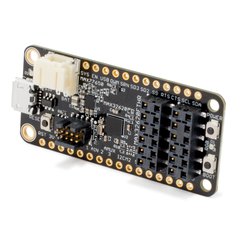
The MAX32620FTHR board is a rapid development platform designed to help engineers quickly implement battery-optimized solutions with the MAX32620 ARM Cortex-M4F microcontroller with FPU. The board also includes the MAX77650 Ultra-low Power PMIC and MAX17055 Fuel Gauge to provide efficient power conversion and battery management with minimal board space. The form factor is a small 0.9in x 2.0in dual-row header footprint that is compatible with breadboards and off-the-shelf peripheral expansion boards. In addition to the dual-row headers, there are also two 12-pin Pmod™-compatible socket connectors for more expansion options. Also on board are common user-interface peripherals including two RGB indicator LEDs and two pushbuttons. These provide a power-optimized flexible platform for quick proofs-of-concept and early software development to enhance time to market.
This pinout and form-factor for this board are based on the Adafruit feather series of boards and it is intended to be compatible with many of their peripheral wings, but it is not guaranteed to work with all FeatherWings.
Pinout

The pinout diagrams above shows the commonly used interfaces and their locations. Note that all the numbered pins (Pn_n) can also be used as DigitalIn and DigitalOut interfaces.
Peripheral Interfaces

The pinout diagrams above shows the commonly used interfaces and their locations. Note that all the numbered pins (Pn_n) can also be used as DigitalIn and DigitalOut interfaces.
PMOD Connector

Features
- MAX32620 Ultra-Low Power Microcontroller
- High performance ARM® Cortex™-M4F Core
- 96MHz, 256KB SRAM, 2048KB Flash
- Ultra-Low Power for Battery Applications
- 62µW/MHz Active Executing from Flash
- 1.06µW Low Power Mode with RTC Enabled
- 2.67µW Ultra-Low Power Data Retention Mode
- 5µs Fast Wakeup to 96MHz
- Peripherals
- USB 2.0 Full-Speed Device
- Three SPI Masters
- Three I2C Masters
- Four UARTs (3 available on platform)
- Sixteen Pulse Train Engines
- Four-Input 10-Bit ADC ADC
- Up to 49 General-Purpose I/O Pins (33 available on platform)
- Tiny 81-Ball 3.948mm X 4.108mm WLP
- MAX77650 Ultra-Low Power PMIC Features
- Smart Power Selector Charger
- Supports Li+/Li-Poly Batteries
- 7.5mA to 300mA Charge Current
- Single Inductor Multiple Output (SIMO) Buck-Boost Regulator
- 3 Outputs from a Single Inductor
- 150mA LDO Regulator
- I2C Configurable
- 2.75mm x 2.15mm, 30-Bump WLP
- Smart Power Selector Charger
- MAX17055 Fuel Gauge Features
- ModelGauge m5 EZ
- Eliminates Battery Characterization
- Eliminates Coulomb Counter Drift
- 7µA Operating Current
- 1.4mm x 1.5mm, 9-Bump WLP
- ModelGauge m5 EZ
- Integrated Peripherals
- RGB Indicator LED
- User push-button
- Evalution Form factor
- 0.9in x 2.0in DIP Form Factor
- Breadboard Compatible
- Feather Wing Compatible
- Pmod-Compatible Sockets
- Supports SPI, UART, I2C, and GPIO
- Accessible from Both Sides of Board
- Power options
- Micro USB Connector (no USB connectivity required)
- JST Battery Connector (Single-Cell Li+ battery)
- 0.9in x 2.0in DIP Form Factor
- Remote mbed DAPLink Debug Interface (included with purchase of MAX32620FTHR)
- [USB MSC] Drag-n-drop programming
- [USB CDC] USB Serial Port
- [USB HID] CMSIS-DAP
Firmware
MAX32625PICO DAPLink Firmware Update
The MAX32620FTHR board ships with an external DAPLink adapter such as the MAX32625PICO. Please visit our MAX32625PICO Firmware Updates GitHub page for details on how to load the correct firmware onto your adapter.
Getting Started with MAX32620FTHR
1. Connect the MAX32620FTHR to the MAX32625PICO
Use the fine pitch 10-pin ribbon cable to connect the boards from the SWD MAXDAP header on the MAX32625PICO to the MAXDAP header on the MAX32620FTHR.
2. Connect the MAX32620FTHR to a power source
Use a micro USB cable to connect the MAX32620FTHR board to a suitable power source (no USB connectivity is required). Alternatively, you can power the board from a charged battery as long as you remember to turn it on by pressing the power/reset button next to the battery connector. The board turns on automatically when powered from the USB supply.
3. Connect the MAX32625PICO to a PC
Use the micro USB cable to connect the MAX32625PICO to a PC. The status light will come on, indicating it has power. After a few seconds of activity, the PC will recognize the MAX32625PICO as a standard USB drive.
 |  |
| Windows XP example | Mac OS X example |
4. Click the MBED.HTM link to get logged in
Go to the new USB Drive, and click MBED.HTM to open it in a web browser. This will take you to the MAX32620FTHR platform page. If you end up at a different page, go to our MAX32625PICO Firmware Updates GitHub page for details on how to load the latest firmware.
If you do not have a mbed account, choose "Signup", and create your mbed Account. Otherwise, login with your mbed username and password.
This will give you access to the website, tools, libraries, and documentation.
PC Configuration
Your mbed Microcontroller can appear on your computer as a serial port. On Mac and Linux, this will happen by default. For Windows, you need to install a driver:
Windows
See Windows-serial-configuration for full details about setting up Windows for serial communication with your mbed Microcontroller
From a host PC to communicate with mbed, you will need a terminal application. This allows the mbed Microcontroller to print to your PC screen, and for you to send characters back to your mbed.
- Terminals - Using Terminal applications to communicate between the Host PC and the mbed Microcontroller
Some terminal programs (e.g. TeraTerm) list the available serial ports by name. However, if you do need to know the identity of the serial port so that you can attach a terminal or an application to it:
| Windows | Mac | Linux | ||||
| Find the identity of the COM port by opening ''Device Manager''. To do this navigate ''Start -> Control Panel -> System -> Hardware -> Device Manager''. | To find the device name under Mac OS X, use the command ''ls /dev/tty.usbmodem*'' | To find the device name under Linux, use the command ''ls /dev/ttyACM*'' | ||||
 |  |  |
Downloading a program
1. Save a program binary (.bin) to the Platform
Download the appropriate "Blinky!" binary:
- MAX32620FTHR: blinky_max32620fthr.bin
Note: the source code for this program will be seen in the next section.
Save the program binary file to your mbed Microcontroller Disk, just like you would with a normal USB disk. The Status LED will flash as the PC writes the file to the Microcontroller disk. The file is now consumed.
2. Press the Reset Button
When the Reset Button is pressed, the microcontroller will be reset and the last programmed application will begin to run.
3. Blinky!
The Microcontroller is now running the program; flashing LED1 forever! If you reset the Microcontroller, or disconnect and reconnect the power, the program will simply restart.
Example Programs
[Repository '/teams/mbed-os-examples/code/mbed-os-example-blinky/' not found]
Where Next
Follow the guide to creating your own programs using the online compiler
Technical Reference
Power
- USB or Battery Powered
- 5.0v from USB available on VBUS (when USB is connected)
- SYS supply automatically switches between battery voltage and VBUS when available
- 1.8V regulated output
- Programmable LDO (typically 3.3V)
- Digital IO pins are individually programmable to 1.8V or 3.3V
Schematics
PCB CAD Files
Data Sheets
You need to log in to post a discussion
Questions
 Neil Panchal
 7 years, 9 months ago
To compile a program for this board using Mbed CLI, use max32620fthr as the target name.
Board Partner
Maxim Integrated
Maxim's microcontrollers provide low-power, efficient, and secure solutions for challenging embedded applications.
 Mbed Enabled
- Baseline
Mbed OS support
- Mbed OS 5.10
- Mbed OS 5.11
- Mbed OS 5.12
- Mbed OS 5.13
- Mbed OS 5.14
- Mbed OS 5.15
- Mbed OS 5.8
- Mbed OS 5.9
- Mbed OS 6.12
- Mbed OS 6.13
- Mbed OS 6.14
- Mbed OS 6.15
Example programs