You are viewing an older revision! See the latest version
nitro_car_project
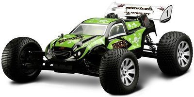
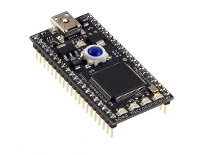
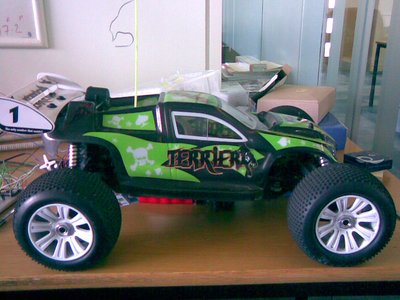
I came to ARM as part of my young apprenticeship and I had little experience of embedded chips and no experience of programming them. On my first couple of days I was playing around with the compiler and the mbed making the LED’s light up. As I got the hang of programming I started to think of a project that I would like to do and that would be useful to me. So I started to think about hobbies I do and an idea jumped out at me. I could improve the technology on my nitro R/C car! I now had an object to improve but I had to think of what to add to it, so I came up with a list:
• Engine temperature
• RPM
• Fuel level
• Speed
• Range finder
• Engine stop
• An accelerometer
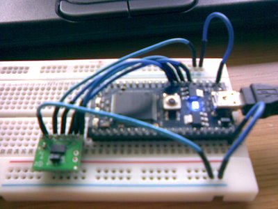
I chose the three that I wanted to do the most and I chose to measure the RPM to make the engine stop if the car flipped and because we needed to use an accelerometer for the engine stop I chose that as well. We also thought that because we have this data it should be saved to a flash drive. We thought because the accelerometer was the most important part we would start with that, we used the LIS302 because it all ready had a library for it and it was easy to use. I wired it up to a LCD display to check the readings where correct but it printed lots or random numbers. I tried to work out what was wrong but in the end I just rewired it up and it worked! I next went on to making a program to work out the RPM there were a couple of things we could have used but we decided to use a QRD1114.
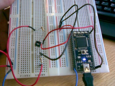
The QRD1114 detects black and white and the voltage is different for each (black is 0-5v and white is 5v+). I had a problem trying to get it to work because I could get it to give readings but they were not right. So I did tests on it and found that the QRD1114 was a dud so as soon as I changed the component it started to work! The penultimate component that I needed to get working was the servo. All I needed to do for this was use the calibration program in the mbed cookbook. To make the engine shut off we needed to make an array so if the accelerometer read a certain value for 2 seconds or more then it would turn the servo 90°. The servo would be attached to a butterfly valve inside the exhaust of the car and when it was closed the car would stop.
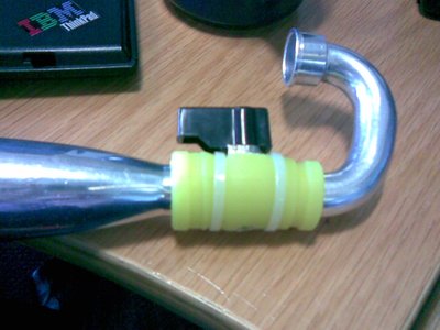

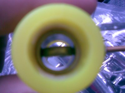
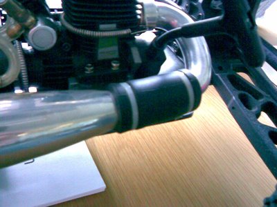
The final thing that I had to do was to get the data to save to a USB memory stick. This was no problem because I only had to change a little bit of my program. So I had made all the programs that I needed all I had to do was put them together (easer said than done). I started by getting the accelerometer and the QRD1114 to save to the flash drive and then I wired up the servo and added the array. The main problems I had was getting pieces of the different program in the right places. I did not think that it mattered but apparently it did. One of the most frustrating things was that the program would run but it would not do what I wanted it to do so I had to go through my program to work out what was wrong.
When we did our first test run on the QRD1114 only read 0RPM all the time so we decided that it could not determine the white and black at 31,000RPM, but there was one upside everything else worked almost perfectly. We decided that the best thing to do was to change the QRD1114 to a photo-interrupter (the KTIR0611S) luckily it worked with the same program so we did not have to make any changes. So I had finished my program. The photo interrupter went on the rear axle as you can see below. We added a bigger grub screw to the axle so it would pass through the photo interrupter showing that it had completed one rotation.
We thought that that it would be a good idea if every time the program made a file it used the RTC as a base for the file name that meant that the data would not be over write and we would know exactly when the file was created. That is why we have a coin cell in the circuit.
This is my finished program and circuit!
http://mbed.org/users/joe/programs/nitrocarproject/latest
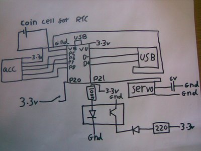
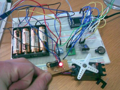
(It’s a bit messy because it is only the prototype!)
This is just a little test I did using my hands to spin the wheel and to move the accelerometer.
/media/uploads/joe/20091503.xls
I have now started making a PCB for my circuit. I have to make two PCBs because the light gate needs to be at the back of the car and the mbed with the other components, I am trying to make the boards as small as possible and I have managed to make the light gate board (KTIR0611S) 27mm x 19mm and the mbed board is 42mm x 79mm. I have been using the free version of eagle ( http://www.cadsoftusa.com/ ) and it has been easy and fun to use. On this soft ware there is a very useful feature called auto router and as you can probably gather it auto routes the signals but I did not use this feature because it was more useful for me to do it myself. The prototypes are going to be made at ARM so we can check that it all works properly and when we are happy that it does what it is meant to it will be sent off so a proper one will be made. The equipment that is used for making the PCBs at ARM is not very accurate so I had to make all the vias bigger than they would normally be. This is so the top and bottom layer of the controller PCB will line up and so it is easier to make because the two layer have to be lined up by eye! This means the prototypes will look slightly different to the final PCB but all the wiring will be the same it will just be a bit bigger.
These are my two boards and schematics


