You are viewing an older revision! See the latest version
lpc11u35_lpc1768_INTERFACE
A breif discussion on how to create a programming interface for the LPC1768 using LPC11U35

Form a starting point I looked through the HDK documrntation, and realised that this is quite a simple circuit.
as my appitite grew, I looked for a way of making it a reality.
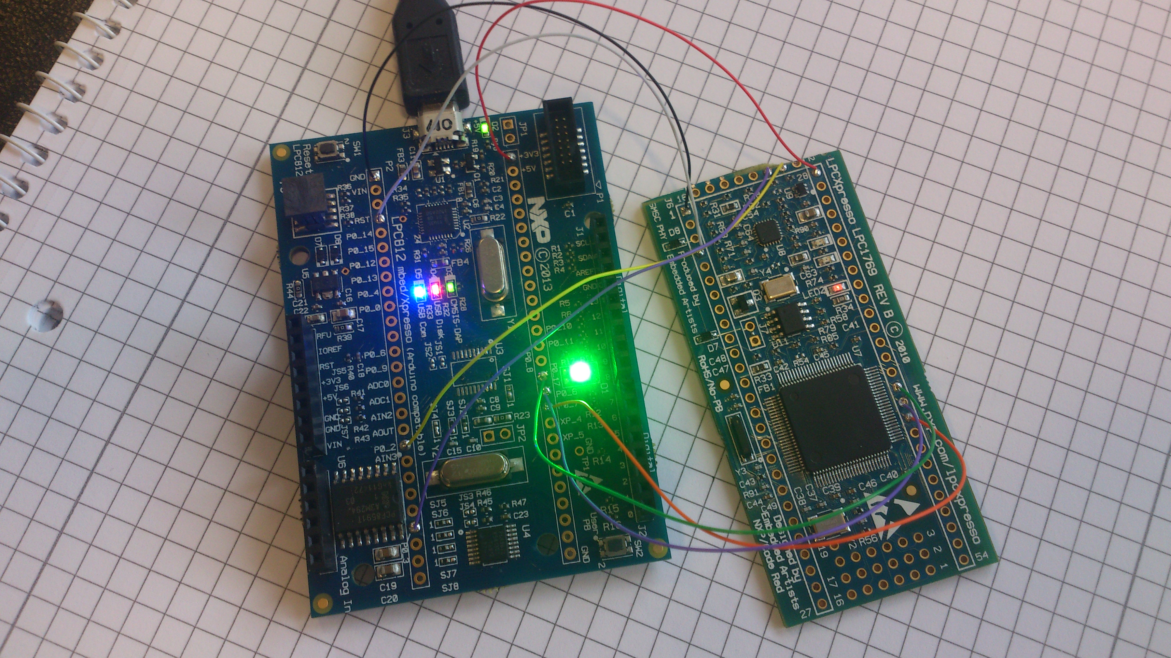
Prior to this, I have been looking through the schematics & datasheets for LPC812-MAX,
supprisingly, I found all the electronics I needed to make a prototype,
Step 1, remove LPC812, and clean pads, so no shorts, Step 2, connect some wires between LPC812-MAX board, and target board, Gnd, 3V3, Reset, SWDIO & SWCLK, - thats all. Step 3, Re-Flash LPC812-MAX with HDK Software, Step 4, reset / unplug, New device appears, and installs stuff. Step 5, compile test program, save to new drive, reset TARGET, job done.
Whats next ?
This is not an ideal solution, as the 'programmer' is quite big and unwelding.
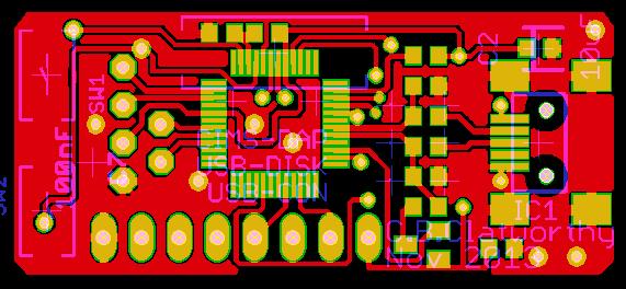
So, design a custom PCB.
Using the HDK demo schematic, I stripped out all but minimal parts, and came up with

I have sent the files off to ragworm PCB So I should have them back and built by the end of November. Unfortuanatly, the PCB was not big enough for the 'MBED Enabled' LOGO !
The pinout I chose was the same as the LPC-Expresso header, that I bucherd some time ago.
but, I think if (when) i desingn a second itteration, then the two unused pins (JTAG uses more pins),
will link through to the CDC Serial.
Also conveniantly matching the FTDI 3V3 serial lead, I have been using for serial programming, which in comparison is PAINFULLY SLOW, less than 2 seconds for SWD, verses more than 30 seconds for a reasnable sized programm.
..