You are viewing an older revision! See the latest version
Reference Design
Download the latest reference designs here https://github.com/ARMmbed/reference-designs
Benefits to Engineers and OEM
Reference Designs are tested and proven starting points targeted towards the creation of Pelion Ready Development Boards and End Products. Designed to provide your product with the IoT subsystem, these Reference Designs can be customized with any sensors and output devices as dictated by your use case thus removing the complexities around connectivity and device management allowing your engineering team to focus on the product key differentiators.
Definition
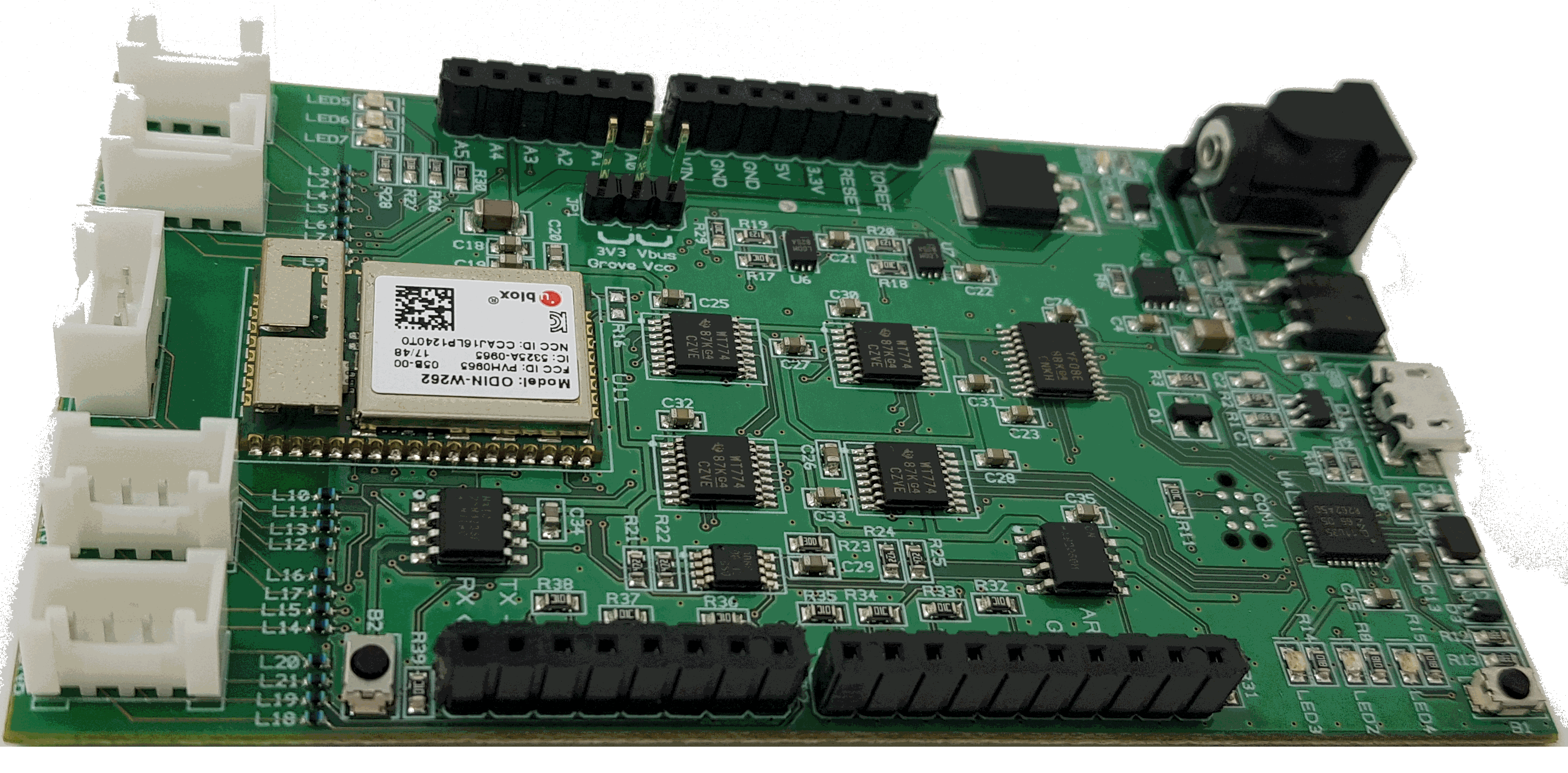
A Reference Designs consists of four main components: Radio, MCU, Memory and secure element; often two or more may be integrated in a single chip by some silicon vendors which goes a long way towards simplifying a design complexity. The design package also contains source code that was used to validate the schematics. Note that a Reference Design isn't a physical board, its the design files; some of our board partners are building hardware based on these proven designs in the form factor they see as most appropriate for their customers, some of these are described later on this page.

Reduced complexity and risk
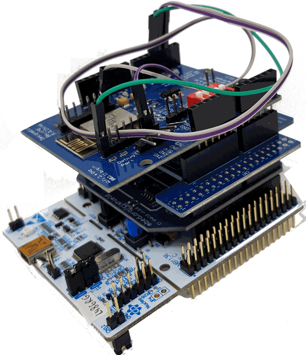
When developing IoT products, an engineer typically selects an MCU development board, adds a shield for connectivity, adds a shield with storage so it will support over the air updates, and selects a secure element; this is all before sensors are even thought about. Then comes the task of finding reliable software that will run with the chosen shield combination. The result is often a cumbersome stack of large boards that look something like this:
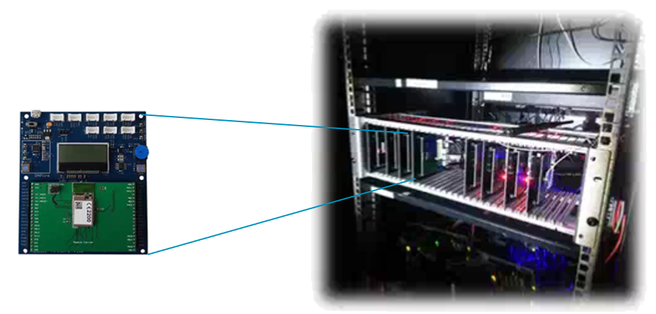
In the Arm validation labs, we have racks full of MCU, Radio, Security and Storage combinations that are used to test each release of Mbed OS before it goes out the door. Some of these combinations are published as schematics on our Reference Design github page so you can be sure that your hardware will perform exactly as we see in our labs.
If you follow the logical design in these schematics your product will be capable of achieving Mbed Enabled and Pelion Ready certifications and therefore compatible with the entire Mbed Ecosystem. Note, these designs are for the IoT subsystem, not a complete end product, you will need to connect input and output devices of your choice but that’s typically very simple because our components page (https://os.mbed.com/components/) already has examples for over 500 different sensors and output transducers.
Take a look at the freely available reference designs already published to see if there is something that meets your needs, if there are any particular combinations you think we are missing, please get in touch so it can be added to the roadmap (https://github.com/ARMmbed/reference-designs).
Some Examples of Boards Based on Reference Designs
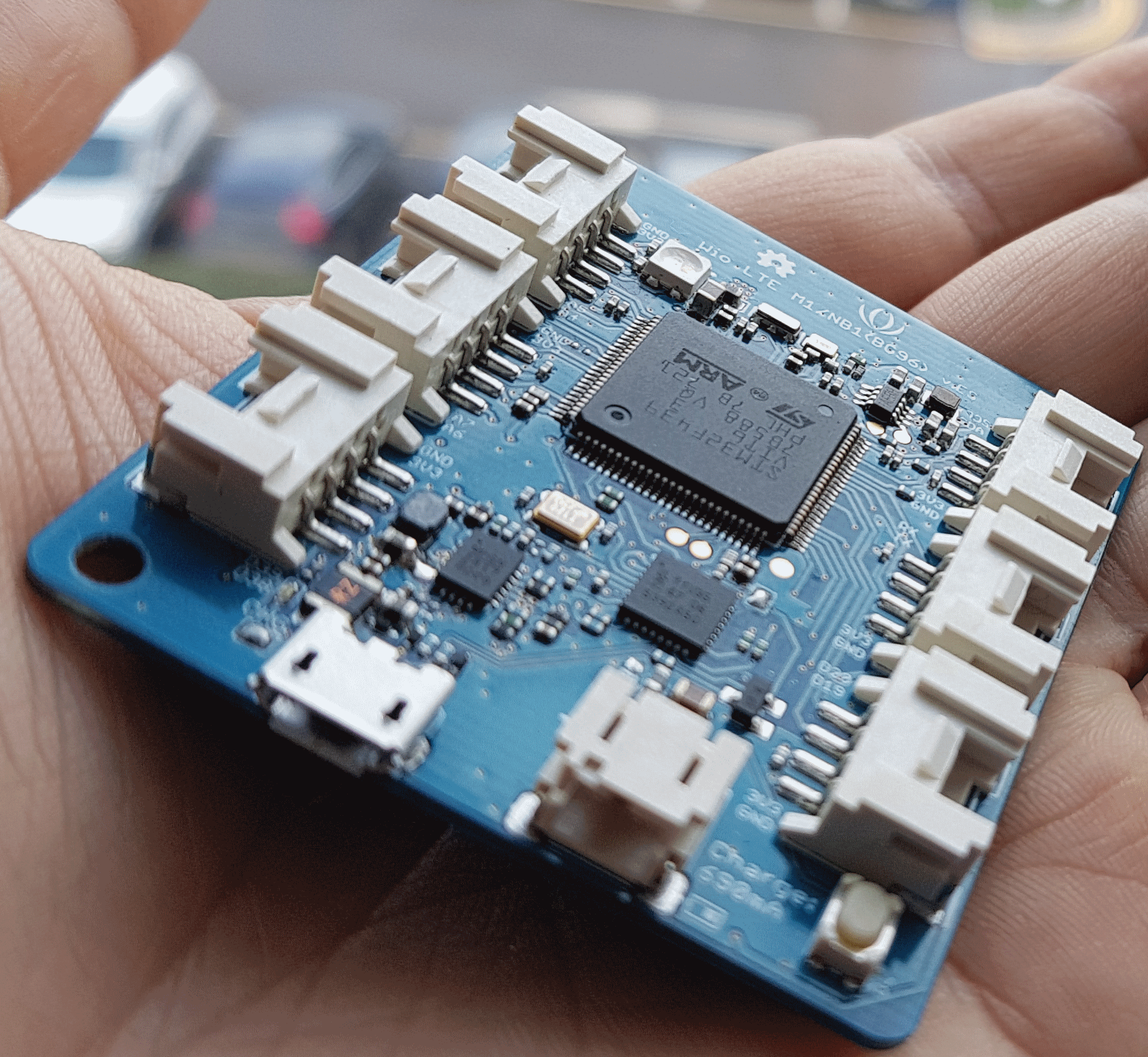
Seed Studio, Wio NB-IoT
- Quectel BG96
- Based on RD2175
- STM32F439
Seed Studio, Wio EMW3166 Wi-Fi
- MxChip EMW3166
- Based on RD1168
- STM32F412 (image coming soon)
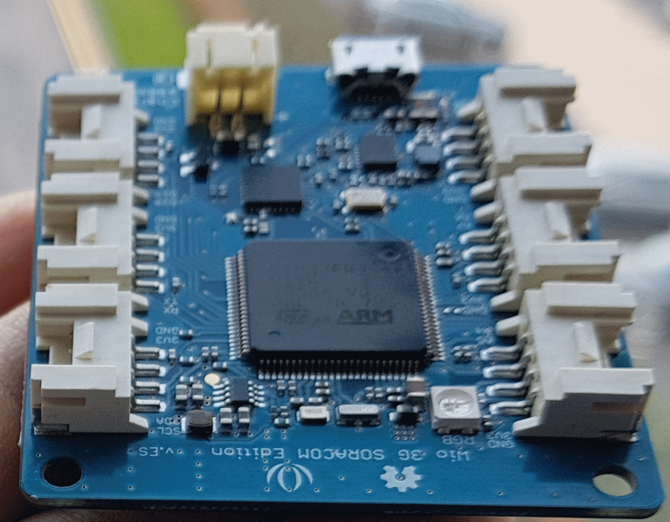
Seed Studio, Wio 3G https://os.mbed.com/platforms/Seeed-Wio-3G/
- Quectel UG96
- Based on RD2729
- STM32F439
Title TBA
- Ublox Odin W2
- Based on RD1552
- STM32F439
