You are viewing an older revision! See the latest version
Prototype To Hardware
Introduction
There has been a lot of questions in the forum about just how easy it would be to move forward from an mbed Microcontroller to actually use the target MCU (NXP LPC1768), avoiding the need to design in £30+ modules
Before showning just how easy it can be, there are a couple of points to make clear:
- You can use the mbed libraries commercially for free, on an unsupported as-is basis
- The mbed compiler generates a raw binary targetting the MCU, there is no bootloader magic going on inthe binary
- The binary runs on the LPC1768 bare metal, there is no runtime environment
- The only magic taking place on the mbed Microcontroller is the "mbed Interface" - It's not actually all that magic, it is just a USB device that can program the raw binary into the LPC1768s flash memory So with that in mind it should be clear that if you wish to take your design to the next stage you can spin your own PCB, solder down the LPC1768 and reuse the binary you made with your mbed Microcontroller prototype, you can.
The purpose is to show you how you can get your binary into the LPC1768 on your own PCB, and what other things you can do.
mbed Prototype
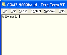
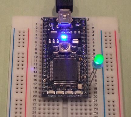
The first thing to do is write a (very) simple program that prints "hello world!" to hyperterminal, and flashes and LED forever. I'll do this on an mbed module first, and then attempt to port it to an LPC1768 on an custom PCB.
I'm driving both ends of the LED as I have a PCB for an LPC1768 that i can port the binary to as an experiment, and doing the double ended driving is the simplest way.
Here is the code :
#include "mbed.h"

Serial pc (USBTX,USBRX);

DigitalOut ledA(p26);
DigitalOut ledK(p24);

int main() {

    pc.printf("Hello world!\n");

    ledK = 0;

    while(1) {
        ledA = 1;
        wait(0.2);
        ledA = 0;
        wait(0.2);
    }
}
Here is the result :
| Teraterm Output | The hardware |
|---|---|
 |  |
Custom PCB
I have a PCB that my brother has spun for an mbed project (programmable access controller). I have put down an LPC1768 and just enough passive to get it running. We'll now see the steps to go through to get the binary that developmed on the mbed prototype running on this LPC1768.
Programming the LPC1768 (theory)
There are two ways to get a binary into the LPC1768; JTAG and the In System Programming (ISP) over a UART using the LPC1768s built-in serial bootloader.
The JTAG method is what you will find on a lot of development boards. It offers many additional features (debug, semihosting, etc) as well as just the ability to load the binary image. Using the JTAG port requires a JTAG "wiggler" to drive the JTAG interface, and some software that knows how to communicate over JTAG and load the binary.
The other method is ISP using the LCP1768 bootlaoder, which relies on a simple strategy:
- Pull nReset low to put the LPC1768 into reset
- Pull the ISP pin (P0.14) low, to indicate the ISP is intended
- Pull nReset high. The LPC1768 comes out of reset and samples the ISP pin. If it is low, the bootloader runs
- The bootloader communicates over a serial connection on UART0: TXD0 = p0.2 = pin 98 ; RXD0 = p0.3 - pin 99
- With a level shifter you can quite happily connect to it from your computers COM port and use teraterm to type commands to it and see the reply, or use some software to communicates and download binaries. The bootloader software uses a series of commands to query the device status, erase, transfer and program binary data to the LPC1768's flash memory. The process is well documented :
- http://www.standardics.nxp.com/support/documents/microcontrollers/pdf/user.manual.lpc17xx.pdf
- Chapter 32, Page 605 onwards it's all there
Life is too short to craft your own way to transferring data by talking to the LPC1768's built in bootloader. Thankfully there are some great apps out there which will do it for you. For the purpose of this example I am using Flash Magic:
- www.flashmagictool.com
Programming the LPC1768 (practice)
The first stop is to get the LPC1768 on the custom PCB into ISP mode, and communicate with it.
Communicating with the LPC1768
To bridge control the pins, and bridge the bootloader serial port to my PC, I will use my mbed as a serial passthrough and to drive the ISP and nReset pins. I'll refer to this arrangement as mbedISP.
- Use GPIO pins (p29,p30) of my mbed to manipulate the nReset and ISP pins on the custom PCB
- Use a serial port (p28,p27) to connect to the bootloader serial port on the LPC1768
- Use the USB serial port to communicate with the PC, and simply pass characters back and forth between the LPC1768 and the PC via the mbed - Think of it as USB -> RS232+Levelshifter ... and then some.. As the nReset and ISP pins have pullups, they should be driven with an open collector. I will mimic this by using a DigitalInOut, driving as an output of value 0, or as an input with no pull-up.