Prototype To Hardware KL25Z
I have started a fresh article for this rather than add to the LPC1768 solution as this is different and and far simpler to do.
I started by braking the track under the J11 connector on the FRDM-KL25Z board to isolate the on-board KL25Z chip and soldered wires to the SWD connector J6 then connected these to my external chip as below.
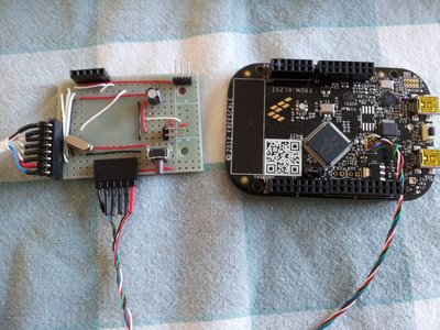
Three connections are required, SWD_DIO (pin2), SWD_CLK (pin4) and RST (pin10). These are the programming connections and I also used the P3V3 (pin1) and GND (pins3 or 5) to power the chip durring programming. I used a 64-pin LQFP version of the KL25Z and connected the coresponding programming pins (PTA3 DIO), (PTA0 CLK) and (RESET_b RST).
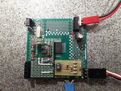
I mounted (lashed up) the chip on a prototype board I had kicking around, added a 8Mhz Xtal with two 22pf capacitors and wired up all the VSS and VDD pins and fitted 0.1uf decoupling capacitors. I also added a reset switch and connectors for my displays and inputs. I looped the VOUT33 pin to the VDD pins of the chip and power the board with an unregulated 5V supply to VREGIN and the display.
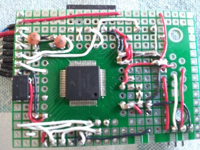
I have also added a 32Khz oscillator chip (left of the picture) as I have yet to work out how to get the internal 32Khz clock signal out to be able to feed back into the RTC clock input (pin PTC1).
Simply compile and save to the FRDM board as normal and the code will be sent to the external chip.
Here is my basic MSF atomic clock working. The chip is very low power only 9mA and the display is 12mA but that depends on LED backlight brightness.
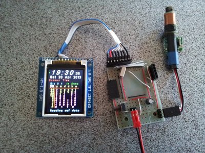
I have had this powered for several days with no problems dispite all the untidy wires around the board.
The cost to do this is minimal, the FRDM board in effect becomes a type of JTAG programmer and can be returned to normal operation by simply connecting J11 again.
As this was a bit messy, I bought some small boards from these guys to try:
http://www.schmartboard.com/index.asp?page=products_clearance&id=274
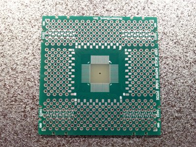
They are double sided that makes it easier to hard wire the connections and at the time of writing they had some clearance boards for only 1$ each. The shipping was a little expensive but they arrived in three days.
I added two seperate boards, i2c RTC clock chip (M41T81) with a back up cell and a temp/humidity chip (SHT-15) using two seperate i2c ports, 8mHz xtal (with two 22pf chip capacitors), reset switch and 5v regulator to power the serial Oled display, and don't forget the decoupling capacitors across the Vss and Vdd as close to the mcu as possible. The on-chip 3.3v regulator is capable for the low power peripheral chips connected.
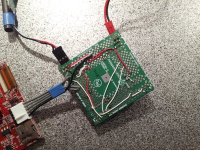
The wiring is underneath now and much more tidy.
Again the code loads just as easy and here is my combined DCF77 - MSF clock running ready to fit to a case.
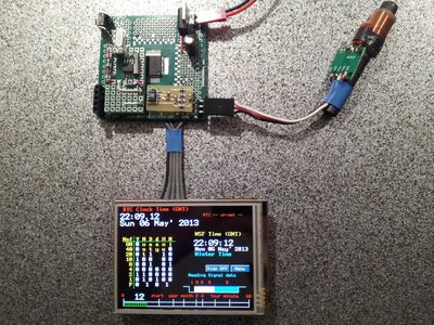
For small one off hardware designs, these boards are a very cost effective way to go. I did get some boards from China but are not as versatile as these. I have mounted two extra small pcb's and there is room for another as well as all the pin outs of the mcu being available to connect to external switches/sensors.