Getting started with mbed LPC1114

If you are good at Japanese than English, here is the Japanese documentation.
/users/ytsuboi/notebook/getting-started-with-mbed-lpc1114-ja/

pin assigns

When you develop LPC1114FN28 with mbed, please refer this pin-out.
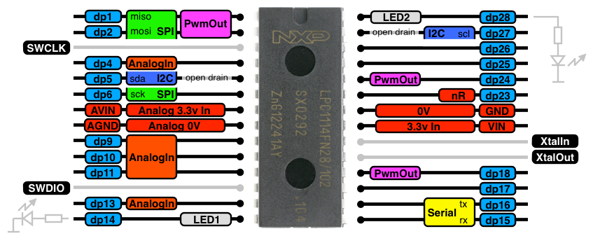
In the near future, we will provide mbed interface for LPC1114, SWD pins were reserved.
So, let's get started from Blinky. I recommend LED2(dp28).

Information

dp5 and dp27 are "open-drain". It's not same as other GPIO pins!!

Where can we get it?

Switch Science (my sponsor!!)
Seeed Studio (my friends!!)
MOUSER
Digikey
element 14

How to flash

There are two ways to flash binaries to LPC1114. One is UART ISP(In-System Programming). And we also have SWD(Serial Wire Debug) option.

ISP

To flash with ISP, you will need a 3.3V UART interface such as Sparkfun's FTDI Basic Breakout.

Warning

You need to check output voltage of your FTDI breakouts/cables before plug-in!!
Some FTDI breakouts/cables output 5V for VCC/VDD even if it outputs 3.3V level UART signal.

Before the flash, you need to connect TX,RX of UART interface to RX(dp15), TX(dp16) of LPC1114FN28.
And, you can put LPC1114FN28 to ISP mode by keeping PIO0_1 (dp24) as low when the MCU reset.
On the picture above, I put a 330ohm resistor between pin24 and GND to make it LOW. Before roasting, put a resistor. And when you see LPC1114 is entered to ISP mode, you need to remove resistor.
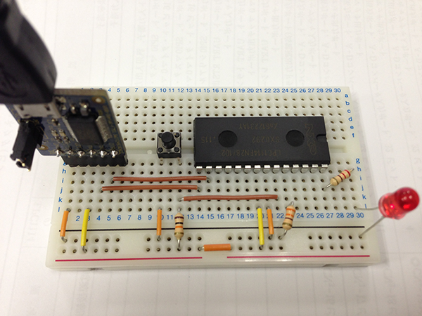
/media/uploads/ytsuboi/lpc1114-isp-blinky.png
Here is the ways to flash with ISP.

ika_shouyu_poppoyaki

ika_shouyu_poppoyaki turns your mbed to ISP programmer.
If you already have blue mbed LPC1768, this is the easiest way to flash LPC1114 with ISP.
Thanks, Okano-san!!

Flash Magic

Flash Magic have GUI and works on both Windows and Mac OS X.
A problem of Flash Magic is, it couldn't load binary!! If you want to flash a binary from online compiler, you need to convert downloaded binary to HEX.
You can convert binary to hex, by using bin2hex on Windows.
On Mac OS X, you can use bin2hex. You need to build runnable binary to use this. (Thanks for this info, Tedd!!)

lpc21isp

I used lpc21isp. lpc21isp could load both binary and HEX.
The lpc21isp binary I'm using on my OS X is here (NO WARRANTY): /media/uploads/ytsuboi/lpc21isp. Please "chmod +x".
I'm using lpc21isp as,
$ lpc21isp -bin LEDBlink_LPC1114.bin /dev/cu.usbserial-AD020SZ2 115200 48000

SWD

If you are SWD user, you will not need my advise.
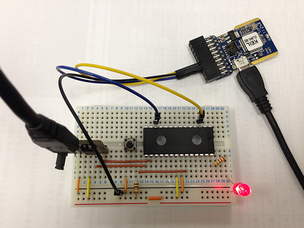
/media/uploads/ytsuboi/lpc1114-swd-blinky.png

Off-line compiling

MDK(uVision 4) is a super AWESOME compiler!! You can get FREE 32kB limited MDK-Lite and enjoy cool debug-enabled developing environment. Since LPC1114FN28 only have 32kB flash, you can enjoy full LPC1114FN28.
We developed this LPC1114 port with this compiler. Armcc in MDK output really small and faster binary.

Now, online compiler could export your project on online to MDK-ARM project.
Here is MDK project archive I distributed when it was not available.
/media/uploads/ytsuboi/1114ledblink.zip

Additional information

We also support LPCXpresso LPC1114. If you want to play with that, please refer this pin-out map. :-)
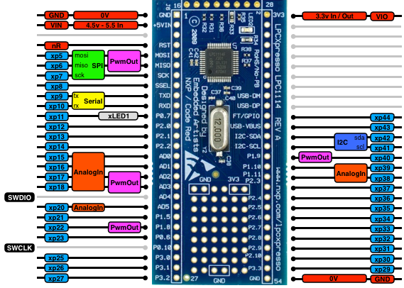
/media/uploads/ytsuboi/pinout_xpresso-20130816-o.png

Credit

The mbed porting for LPC1114 was being done by following member,

And, here is supporters.

Feedback

If you find any problem on this porting, please let me know by dropping a comment on this page. Or, you can contact me by Twitter ( @ytsuboi ) or Facebook.


36 comments on Getting started with mbed LPC1114:

03 Sep 2013

Dear Yoshihiro, I found PwmOut is not working properly, I tried dp10,dp11,dp17,dp18 pins to output PWM, but all failed, I can't measure the PWM waveform on these pins, besides if I used dp17, the CPU will hang. Below is my testing code: (Note: the serial output is working properly)

Please give me some advice, thank you very much. Best regards, Stanly

PwmOut testing code of LPC1114FN28

#include "mbed.h"

PwmOut led(dp18);
Serial pc(dp16,dp15);

int main()
{
    float fR0 = 0.0;
    led = 0.0;
    
    pc.baud(115200);
    pc.printf("LPC1114 demo PWM\r\n");
    
    while(1)
    {
        led = led + 0.01;
        fR0 = led;
        pc.printf("led duty = %f\r\n", fR0);
        wait(0.2);
        if(led >= 1.0)
        {
            while(1)
            {
                led = led - 0.01;
                wait(0.2);
                fR0 = led;
                pc.printf("led duty = %f\r\n", fR0);
                if(led <= 0.0)
                {
                    led = 0.0;
                    break;
                }
            }
        }
    }
}
03 Sep 2013

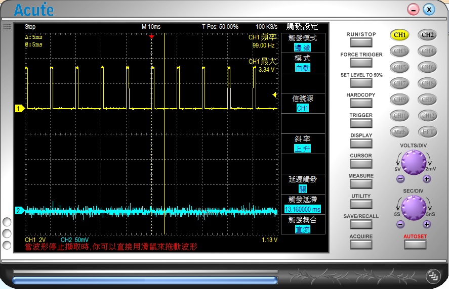
Dear Sir, By the way, I wrote another test code to verify dp10,dp11,dp17,dp18 to verify the Digital output, and I can measure the toggle 'High' to 'Low' waveform of all these pins. See the test code and measure waveform photo below:

Test Digital output on dp10,dp11,dp17,dp18

#include "mbed.h"

//#define PWM_TEST
#define DIGITAL_OUT_TEST

#ifdef PWM_TEST
PwmOut led(dp18);
#endif

#ifdef DIGITAL_OUT_TEST
BusOut DO(dp10,dp11,dp17,dp18);
//DigitalOut DO1(dp10);
#endif
Serial pc(dp16,dp15);


int main()
{
    #ifdef PWM_TEST
    float fR0 = 0.0;
    led = 0.0;
    #endif

    pc.baud(115200);
    pc.printf("LPC1114 demo PWM\r\n");
    
    while(1)
    {
      #ifdef PWM_TEST
        led = led + 0.01;
        fR0 = led;
        pc.printf("led duty = %f\r\n", fR0);
        wait(0.2);
        if(led >= 1.0)
        {
            while(1)
            {
                led = led - 0.01;
                wait(0.2);
                fR0 = led;
                pc.printf("led duty = %f\r\n", fR0);
                if(led <= 0.0)
                {
                    led = 0.0;
                    break;
                }
            }
        }
      #endif

      #ifdef DIGITAL_OUT_TEST
        DO = 0x0F;
				wait(0.001);
				DO = 0;
				wait(0.009);
      #endif
    }
}

/media/uploads/stanly88/pwm_pin_do_test.jpg

03 Sep 2013

Chen-san, I'm sorry. Pin-out picture was wrong. We can't use dp17 for PWM. It's spec of LPC1114.

05 Sep 2013

Chen-san, we confirmed there are problem around PWM. We are still investigating the cause. Please give us a few days.

06 Sep 2013

Dear Yoshihiro, Thank you very much for your reply.

By the way, I found PwmOut is working properly on dp1, and dp2 pin.

I also found why dp10 and dp11 are not working, because these 2 pins are control by CT32B1, but CT32B1 is used by mbed library: mbed-src\targets\hal\TARGET_NXP\TARGET_LPC11XX\us_ticker.c, so that is the reason why dp10 and dp11 don't work.

Finally, we only need to figure out why dp18 PwmOut is not functional. Thank you again for helping to solve PwmOut issue.

Stanly

06 Sep 2013

Dear Yoshihiro,

I found the LPC1114 porting, CPU clock is running at 12MHz, would you please change it to 48MHz? Since mbed is a C++ framework library, we need CPU to run at highest possible frequency for getting better performance.

Thank you very much. Stanly

06 Sep 2013

Chen-san,

about CPU clock, I already found, solved and comitted that problem. Please wait a moment to be adapted that patch.

06 Sep 2013

Dear Yoshihiro, Thank you for replying the CPU Clock question.

I found the root cause of PwmOut Issue, the source file:

mbed-src\targets\hal\TARGET_NXP\TARGET_LPC11XX\pwmout_api.c

PinMap_PWM look-up table, data member: peripheral, PWM_1, PWM_2 are okay, but from third element of array, PWM_4, it indexed to a wrong Timer ID of pwm_timer_map[ ].

Here I attached original code, and the fixed code as below:

original pwmout_api.c

static const PinMap PinMap_PWM[] = {
    /* CT16B0 */
    {P0_8 , PWM_1, 0x02},   /* MR0 */
    {P0_9 , PWM_2, 0x02},   /* MR1 */

    /* CT16B1 */
    {P1_9 , PWM_4, 0x01},   /* MR0 */
    {P1_10, PWM_5, 0x02},   /* MR1 */

    /* CT32B0 */
    {P1_6 , PWM_6, 0x02},   /* MR0 */
    {P1_7 , PWM_7, 0x02},   /* MR1 */
    {P0_1 , PWM_8, 0x02},   /* MR2 */

    /* CT32B1 */
    {P1_1 , PWM_9 ,0x03},   /* MR0 */
    {P1_2 , PWM_10,0x03},   /* MR1 */

    {NC   , NC    ,0x00}
};

Fixed pwmout_api.c

static const PinMap PinMap_PWM[] = {
    /* CT16B0 */
    {P0_8 , PWM_1, 0x02},   /* MR0 */
    {P0_9 , PWM_2, 0x02},   /* MR1 */

    /* CT16B1 */
    {P1_9 , PWM_3, 0x01},   /* MR0 */
    {P1_10, PWM_4, 0x02},   /* MR1 */

    /* CT32B0 */
    {P1_6 , PWM_5, 0x02},   /* MR0 */
    {P1_7 , PWM_6, 0x02},   /* MR1 */
    {P0_1 , PWM_7, 0x02},   /* MR2 */

    /* CT32B1 */
    {P1_1 , PWM_8, 0x03},   /* MR0 */
    {P1_2 , PWM_9, 0x03},   /* MR1 */

    {NC   , NC    ,0x00}
};

Thank you very much. Best regards,

Stanly

16 Dec 2013

I have a FTDI TTL-232R-3V3 cable and it looks as if the pinout is right for the plugblock shown, but the cable outputs 5v from the USB port directly, it does not include a regulator.

07 Jan 2014

Maybe a small jumper (solder via) on the FTDI board which gives you the option to switch between 5V en 3V3?

07 Jan 2014

Oliver Broad wrote:

I have a FTDI TTL-232R-3V3 cable and it looks as if the pinout is right for the plugblock shown, but the cable outputs 5v from the USB port directly, it does not include a regulator.

You are right. I've checkout datasheet of FTDI TTL-232R-3V3, and it shows its VCC is 5V. FTDI TTL-232R-3V3 users need to think about power supply.

Jan Kampen wrote:

Maybe a small jumper (solder via) on the FTDI board which gives you the option to switch between 5V en 3V3?

Yes, FT232RL have a +3.3V LDO and it could regulate upto 50mA. If your breakout/adapter can provide this 3.3V, you can use that for small projects.

08 Jan 2014

Hello,

I am trying to control some leds on the LPC1114FN28. P0_7 works fine, and P0_3 also, but the P0_4 (SCL) pin is not able to let the LED blink. Is this by design? Accoring to the datasheet of the controller it should be able to use this pin as general output.

Code:

  1. include "mbed.h"

DigitalOut led (P0_4);

int main() { while(true) { led = 1; wait(0.5); led = 0; wait(1.0); } }

Kind regards, Jan Kampen

08 Jan 2014

Hi Jan,

Jan Kampen wrote:

I am trying to control some leds on the LPC1114FN28. P0_7 works fine, and P0_3 also, but the P0_4 (SCL) pin is not able to let the LED blink. Is this by design? Accoring to the datasheet of the controller it should be able to use this pin as general output.

PIO0_4 and PIO0_5 are open-drain ports. You can find this information on NXP's user manual Rev. 9.1 http://www.nxp.com/documents/data_sheet/LPC111X.pdf page 25 of 126, table 7.

So, if you want to let the LED blink with these ports, you should better to connect Cathode of LED to LPC and Anode to VCC via current limiting resistor.

10 Feb 2014

I am looking to use the LPC1114FN28 in the next few days. I have been looking at the user manual and found that SPI0 has a SSEL0 pin PIO0_2. Is this pin active when using SPI0 or can it be used as a GPIO?

Dave.

11 Feb 2014

Question now moved to forum Bugs & Suggestions.

Dave.

16 Feb 2014

Hi,

I am new to programming and have developed a program for a FRDM board on Mbed, which I would like to convert to a single chip MCU.

Am I right in thinking that using the LPC1114, it is as simple as:

1. Adjusting the program for the new chip 2. Downloading the Mbed.bin file 3. Converting to a .hex file 4. Uploading to the chip using Flash Magic?

Please let me know if this is incorrect, and what the simplist method to do this would be.

Thank you

16 Feb 2014

Hi Jonathan,

Jonathan May wrote:

Am I right in thinking that using the LPC1114, it is as simple as:

1. Adjusting the program for the new chip 2. Downloading the Mbed.bin file 3. Converting to a .hex file 4. Uploading to the chip using Flash Magic?

Yes, it is very easy to port a program from FRDM to LPC1114 if you are using mbed. :-) You can write/flash/burn downloaded .bin file to LPC by ISP or SWD. If you want to use Flash Magic, you need to convert to .hex file before flashing. So, you are right.

Probably, most simple way is Flash Magic.

19 Feb 2014

Hi! I'm sorry if this might be a noob question, but at what frequency does the IC run? I saw in Flash Magic that you can set the frequency to 12MHZ, how do I set it to run at its max frequency? Thank you! :)

19 Feb 2014

Flash Magic does not set the device frequency. The 12 MHz you see is for a crystal. The lpc1114fn28 is already running at it's max at 48MHz.

Dave.

19 Feb 2014

Thanks David. :-)
12MHz on FlashMagic is right choice. This is about ISP mode.
When the binary developed on mbed running, LPC1114FN28 runs at 48MHz. It is from 12MHz internal RC oscillator and divided by 4 at System PLL.
This clock setting was configured at system_LPC11xx.c included in mbed library.

20 Feb 2014

Thank you very much! :D

19 May 2014

Is the default clock set up using IRC or external crystal source? I assume the crystal frequency would be 12Mhz. Can this be selectable in the Mbed-SRC system_LPC11xx.c library file. If so what would be the necessary changes to select the different clock set up's?

11 Jul 2014

Hi guys,

just got my mbed LPC1114FN28 from SWITCH SCIENCE.

Is it just plug and play like f.e. the mbed LPC11U24?

I tried to start with blinky on p28. But i cant get it working. Does my usb 5V supply the LPC1114 or do i need a second power support? 3.3 volt ?

Thanks

06 Aug 2014

um... Hi~ when I... hex file download after compile, show this error

Set Device Failed ! Error info: Device XML file not find

how can I solve this?

19 Aug 2014

Dear All,

May i know where can i buy this SWD tools?

Thank you.

22 Aug 2014

Daniel Trojer wrote:

Is it just plug and play like f.e. the mbed LPC11U24?

I tried to start with blinky on p28. But i cant get it working. Does my usb 5V supply the LPC1114 or do i need a second power support? 3.3 volt ?

Thank you. Yes, you just need to plug like mbed LPC11U24. The power for the MCUs will be supplied from USB.
Did you connect LED and current limit resistor? The LED on board is not connected to LPC1114FN28. The one is for indicator of interface chip.

John Doe wrote:

um... Hi~ when I... hex file download after compile, show this error

Why hex file? I believe you can download binary file when you get built your project successfully.

Wen qian wrote:

May i know where can i buy this SWD tools?

Is that meaning software tools? There are
A) MDK-ARM http://www.keil.com/arm/mdk.asp It's expensive but high productivity compiler. You can build smaller than 32KB binary with free MDK-Lite.
B) pyOCD or OpenOCD https://github.com/mbedmicro/pyOCD http://openocd.sourceforge.net
This solution may need some hassle. If you are familiar with Cortex developing solutions, you could be happy with these.

If you are mentioning about debug adapter, you can buy through Switch Science, or its distributors.
http://international.switch-science.com/catalog/1714/
http://www.seeedstudio.com/depot/Mbed-LPC1114FN28-ARM-CortexM0-p-1879.html?cPath=6_11

22 Oct 2014

I'm considering to use mbed platform for a project I began writing with a Spark Core.

The Spark Core is a great product for writing IoT, but when you need to work without internet it falls short. It's also more expensive when you try to scale your project.

The mbed online IDE very nice, but it's pretty hard to find information on how to flash these things.

Using the debug adapter is possible to flash programs? It's something like: pressing the ISP button and using FlashMagic? Is it possible to debug an application using the debug adapter?

05 Nov 2014

Hi ytsuboi,

I'm getting a weird error using serial printf with the LPC1114. There is a lot of unexpected delays when I try to print out numbers through serial. I have posted more details in the question below, maybe you might have some idea what is going wrong?

http://developer.mbed.org/questions/5149/Serial-port-on-LPC1114-is-slow/

I have updated the firmware to the latest Version: 0203 Build: Jun 21 2014, so that shouldn't be the cause. Thank you for any information you might have on this issue.

11 Nov 2014

Hi Stanly & Yoshihiro san,

I found latest code from mbed in github has changed as following:

/* To have a PWM where we can change both the period and the duty cycle,
* we need an entire timer. With the following conventions:
* * MR3 is used for the PWM period
* * MR0, MR1, MR2 are used for the duty cycle
*/
static const PinMap PinMap_PWM[] = {
/* CT16B0 */
{P0_8 , PWM_1, 0x02}, /* MR0 */
{P0_9 , PWM_2, 0x02}, /* MR1 */
/* CT16B1 */
{P1_9 , PWM_3, 0x01}, /* MR0 */
{P1_10, PWM_4, 0x02}, /* MR1 */
/* CT32B0 */
{P0_1 , PWM_5, 0x02}, /* MR2 */
{NC , NC ,0x00}
};

So there are only 5 PWM available now? Even less than previous version? I know CT32B1 has been used as system clock. But in LPC1114 QFP version, there are more channels available.

And in LPCXpresso pinout, some PWM outputs are CT32B1 MAT output.

Wrong PWM marking in LPCXpresso pinout

  • XP5/MOSI->CT16B0_MAT1
  • XP6/MISO->CT16B0_MAT0
  • XP17/AD2->CT32B1_MAT0
  • XP18/AD3->CT32B1_MAT1
  • XP22/P1.8->CT16B1_CAP0
  • P1.9->->CT16B1_MAT0

The real PWM output available on LPC1114FDB48/301 or 302 should be (excluded CT32B1):

  • P0.8->MISO (marked as miso, supported in code)
  • P0.9->MOSI (marked as mosi, supported in code)
  • P0.10->SWCLK
  • P1.6->RXD (only as rx, not support in code)
  • P1.7->TXD (only as tx, not support in code)
  • P0.1/CLKOUT/CT32B0_MAT2 (marked as XP44, not in PWM, silkscreen as FT/GPIO, supported in code)
  • R/P0.11/AD0/CT32B0_MAT3 (marked only as XP15/AD0, not in PWM, not support in code)
  • P1.9/CT16B1_MAT0 (marked as XP40 and PWM, supported in code)
  • P1.10/AD6/CT16B1_MAT1 (marked as XP39, not in PWM, supported in code)

Therefore, the pinout of LPC1114 should be revised, and P0.11 should be added for PWM as CT16B1 output.

06 Dec 2014

Hi, Couple days before I started playing with mbed LPC1114FN28 and found one issue. I'm not able to use dp5 and dp27 (I2C open drain pins) as DigitalOutputs. Code is compiling, but direct measure of voltage gives always GND voltage there. Any reason for that?

Thanks in advance, Fosfor

18 Dec 2014

Hi Tomasz,

Did you provide pull-up resistors for those 2 pins ?

24 Feb 2015

The link for bin2hex appears to be invalid now. I think this is usable: http://www.ht-lab.com/freeutils/bin2hex/bin2hex.html

Also I downloaded the source for lpc21isp and compiled it OK. I also made a short batch file to automatically transfer MBED binaries:

if $%1==$ ( "%dp0lpc21isp.exe" pause ) else ( "%dp0lpc21isp.exe" -bin "%1" com2 9600 48 if errorlevel 1 pause )

that you can put in the same folder as the "exe". Then if you associate the "bin" file extension with the batch file the binaries from MBED automatically launch the programmer. Change "com2" to whatever port number you use.

19 Nov 2015

Edit: I got it working!!!

04 Apr 2016

I know this has been gone over before but what is the correct clock number to use with lpc21isp? If I'm accessing ISP by resetting it into ISP the bootloader will have configured itself to a default RC configuration. Under those conditions does the bootloader even care what number is passed since the clock configuration is known anyway?

I used "48" and various other numbers when I probably should have sent "48000" but nothing broke.

Presumably 48000 (48MHz) would be the correct value to use for ISP mode when called from an application via IAP?

14 Feb 2017

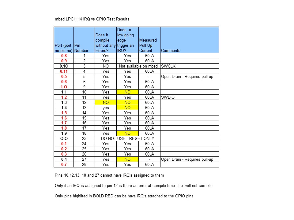
LPC1114 IRQ pin assignments - for info

/media/uploads/andrewcrussell/slide1.jpg

24 Sep 2022 This post is awaiting moderation

I think this page just change io pin block image, to clarify SPISlave chipselect pin is avaiable on dp25.

Please log in to post comments.