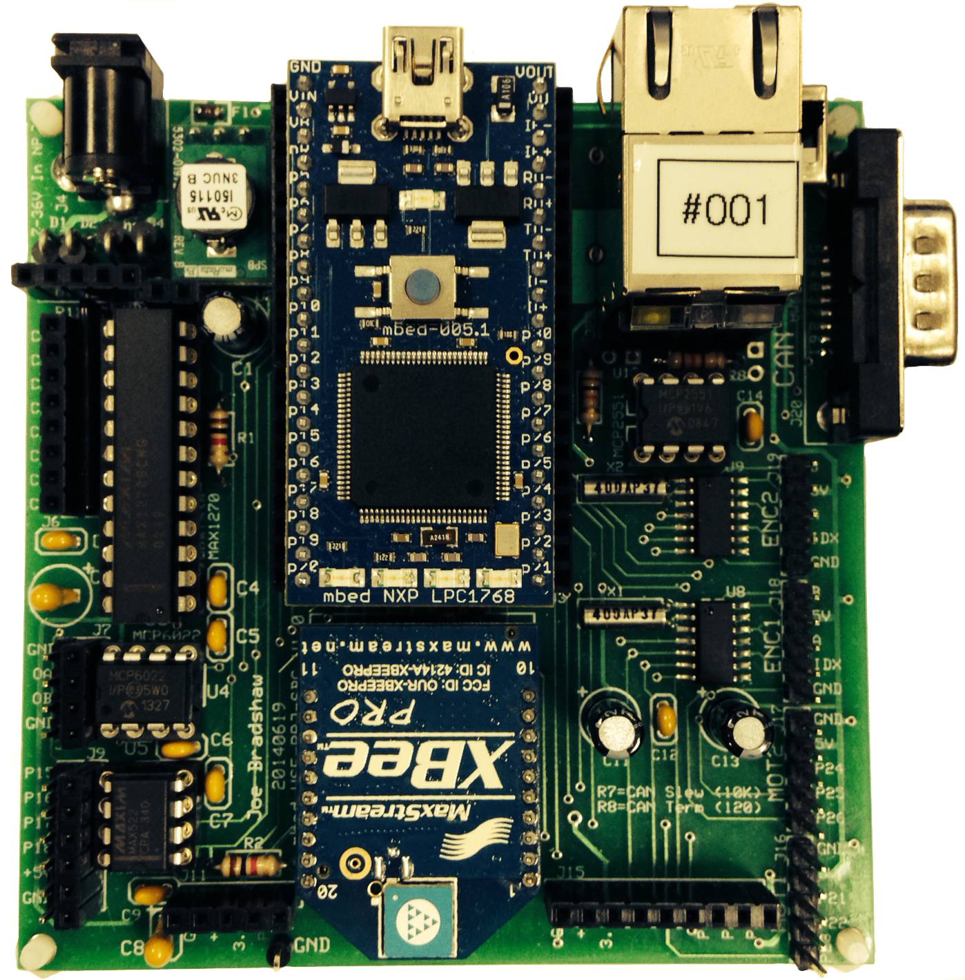
C Library for mbedWSE project based single board computer for hardware peripherals
Dependents: Lab7_wse Lab7_wse_student mbed_WSEPRJSBC_EncoderTest mbed_WSEPRJSBC_ADC_test ... more
Weapons and Systems Engineering mbed based single board computer

Contains C library function listing for hardware peripheral support. Includes functions for +/-10V 12-bit 8-Channel analog-to-digital converter (ADC), 10-bit 2-Channel digital-to-analog converter (DAC), motor control/servo ports, and quadrature encoder ports. Board includes physical Ethernet, USB Host, and CAN bus interfaces. Also includes xbee socket and external I/O pins straight to processor for on-board I2C, SPI, ADC, and DAC.
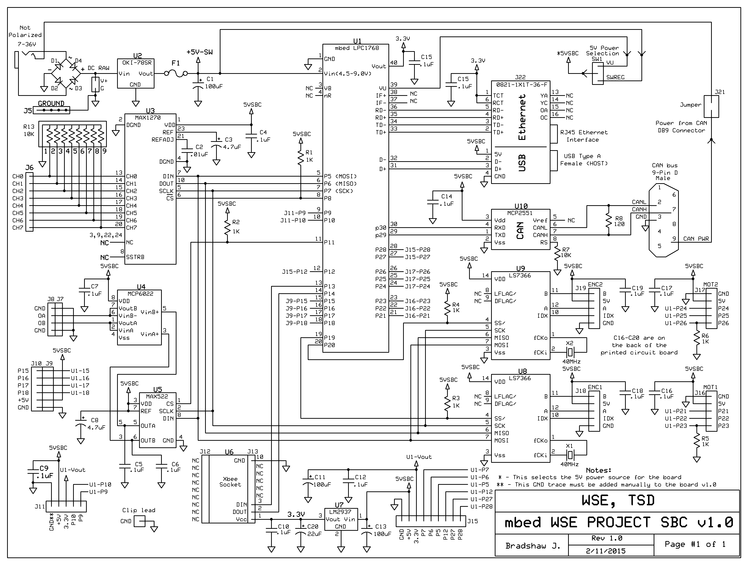
Schematic

Description
This single board computer was designed for the Weapons and Systems Engineering department at the US Naval Academy. The board encompasses a multitude of functional capability for interfacing to a variety of sensors and actuators used in embedded control systems. The board can be powered from a 7-36V DC / AC power supply using a 2.1mm standard barrel connector. The on board bridge rectifier composed of individual diodes allows either polarity on the connector power supply. The four primary external integrated circuits on the board all use the SPI bus for communication. The four primary components are the analog to digital converter, the digital to analog converter, and the two dedicated encoder/counter IC's. The encoder/counter IC's off-load the micro-processor from the burden of external interrupts during high frequency edge detection. The IC's offer 32-bit resolution counting/quadrature decoding, rollover and status information, and index detection for absolute position encoder interfacing. The MAX1270 analog to digital converter (ADC) was chosen for its internal reference and bi-polar voltage input range and scaling program-ability (0-5V, 0-10V, +/-5V, +/-10V). The ADC provides 12-bit resolution at these voltage ranges and are individually channel select-able. Note that careful attention must be used when driving the ADC inputs when in Bipolar operation. An Op-Amp with insufficient current drive capability (milli-amps) will be unable to overcome the internal voltage reference on the input pin due to impedance mismatch/ output current drive capability. This should be checked with an oscilloscope on the input pin if discrepancies between measured voltage values and ADC results exist.
The MAX522 DAC provides 0-5V 10-bit voltage resolution. The range is dependent on the selected 5V board voltage reference source (external 5V switching regulator vs. USB power supply). The board power supply 5V reference can be read by connecting the supply to an external ADC channel and reading the voltage on the 0-10V range.
/media/uploads/jebradshaw/mbed_wseprojsbc_schematic_20140922.pdf - Schematic in PDF
Test Program
/media/uploads/jebradshaw/main_mbedwsesbctest.cpp - Program for testing the library, control the SBC with serial commands
http://developer.mbed.org/users/jebradshaw/code/mbed_WSEPRJSBC_EncoderTest/ - Program for testing the Quadrature Encoder Channels
http://developer.mbed.org/users/jebradshaw/code/mbed_WSEPRJSBC_ADC_test/ - Program to read two channels from the MAX1270 ADC in +/- 10V operation.
http://mbed.org/handbook/Windows-serial-configuration - Link to Serial Driver Installation instructions
Datasheets
/media/uploads/jebradshaw/oki-78sr.pdf - 5V switching regulator
/media/uploads/jebradshaw/ls7366r_w_program.pdf - Encoder IC's
/media/uploads/jebradshaw/max1270.pdf - ADC 8-Channel 12-bit 5V to 10V single/bi-polar input
/media/uploads/jebradshaw/max522.pdf - DAC 2-Channel 0-5V 10-bit
/media/uploads/jebradshaw/mcp2551_can_transceiver.pdf - CAN Transceiver
/media/uploads/jebradshaw/0821-1x1t-36-f.pdf - Ethernet Jack
/media/uploads/jebradshaw/190-009-263r001.pdf - CAN connector
Printed Circuit Board (ExpressPCB)
/media/uploads/jebradshaw/mbedprjv10_20140916.pcb
Partslist (partial)
/media/uploads/jebradshaw/mbedprjv10_partslist.pdf
History
updated comments
2016-10-11, by jebradshaw [Tue, 11 Oct 2016 17:13:09 +0000] rev 14
updated comments
Changed MAX1270 SCLK to 5MHz (datasheet pulse width high 200ns, pulse width low 200ns) Changed SPI mode to format(12, 0) during conversion
2016-10-11, by jebradshaw [Tue, 11 Oct 2016 17:11:12 +0000] rev 13
Changed MAX1270 SCLK to 5MHz (datasheet pulse width high 200ns, pulse width low 200ns) Changed SPI mode to format(12, 0) during conversion
pre-defined DigitalOut logic levels
2015-02-10, by jebradshaw [Tue, 10 Feb 2015 16:14:18 +0000] rev 12
pre-defined DigitalOut logic levels
Initialize DigitalOut's with pre-defined logic states (CS's high, etc)
2015-02-10, by jebradshaw [Tue, 10 Feb 2015 16:05:18 +0000] rev 11
Initialize DigitalOut's with pre-defined logic states (CS's high, etc)
Commented out PWM period declaration and updated comments
2014-11-03, by jebradshaw [Mon, 03 Nov 2014 20:08:48 +0000] rev 10
Commented out PWM period declaration and updated comments
Removed PWM period declaration from library.
2014-11-03, by jebradshaw [Mon, 03 Nov 2014 20:04:52 +0000] rev 9
Removed PWM period declaration from library.
Removed PWM period decleration from SBC Init() function.
2014-11-03, by jebradshaw [Mon, 03 Nov 2014 20:02:00 +0000] rev 8
Removed PWM period decleration from SBC Init() function.
PID control Quanser active suspension demo
2014-10-22, by jebradshaw [Wed, 22 Oct 2014 19:09:00 +0000] rev 7
PID control Quanser active suspension demo
mbed WSE SBC program to test the quadrature encoders
2014-10-16, by jebradshaw [Thu, 16 Oct 2014 17:37:56 +0000] rev 6
mbed WSE SBC program to test the quadrature encoders
20140925 - Updated with Encoder test program
2014-09-25, by jebradshaw [Thu, 25 Sep 2014 13:54:20 +0000] rev 5
20140925 - Updated with Encoder test program