Bluepill STM32F103C8 support for Mbed OS 6
Bluepill board support for Mbed OS 6
Warning
It does not work with the Mbed Online Compiler.
This is an example of configuration for the Bluepill board for Mbed OS 6.
It shows how to create a custom board support based on Mbed OS and how to compile a simple Blinky application.
Note this project makes use of the full Mbed OS with RTOS included. It's possible to make changes in the configuration to support the Baremetal profile and reduce memory requirements - see this.
Example application
This repository includes blinky.cpp as an example application to demonstrate how to use the Bluepill custom board support. It's expected to work out of the box using both Mbed CLI and Mbed Studio.
Note this test application can be ignored using the MBED_BLINKY_EXAMPLE macro in mbed_app.json, so you can add your own files and application on top of this project.
You can follow these steps to import and compile with Mbed CLI:
mbed import https://os.mbed.com/users/hudakz/code/mbed-os-bluepill
mbed compile -t GCC_ARM -m bluepill
Bluepill and Mbed OS version support
| Bluepill | Mbed OS (hash) | Status |
|---|---|---|
| preview | 6.2.0 (#a2ada74770 ) | Compiles and runs ok |
Updating Mbed OS
Note not every version of Mbed OS is being tested, therefore update at your own risk. Unless strictly required, you should stick to versions of Mbed OS that are known to work ok.
If you do want to udpate Mbed OS, then follow these steps:
cd mbed-os
mbed update <mbed-os hash / tag>
Testing
This application has been tested on the Bluepill board and runs ok: it blinks and LED and sends a message over the serial port (115200 bauds - see mbed_app.json).
However, it's recomended to run regression tests based on the Greentea framework whether possible (more details to be added).
Programming with STLink programming utility
The Bluepill board doesn't have a programming interface on board. However, it's easy to connect an external adapter such as the STLink/V2 and get it working in minutes.
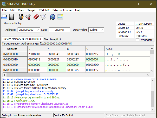
Use the STM32 ST-Link utility to program the binary into the device.

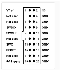
Wire the Bluepill to the STLink and serial adapter as follow:
| Bluepill | STLink (20-pin JTAG) | Serial adapter |
|---|---|---|
| SDWIO (CN4) | 7 | - |
| SWCLK (CN4) | 9 | - |
| RESET | 15 | - |
| GND | 4 | GND |
| TX (PA_2) | - | RX |
| RX (PA_3) | - | TX |
ST-LINK/V2 JTAG pintout

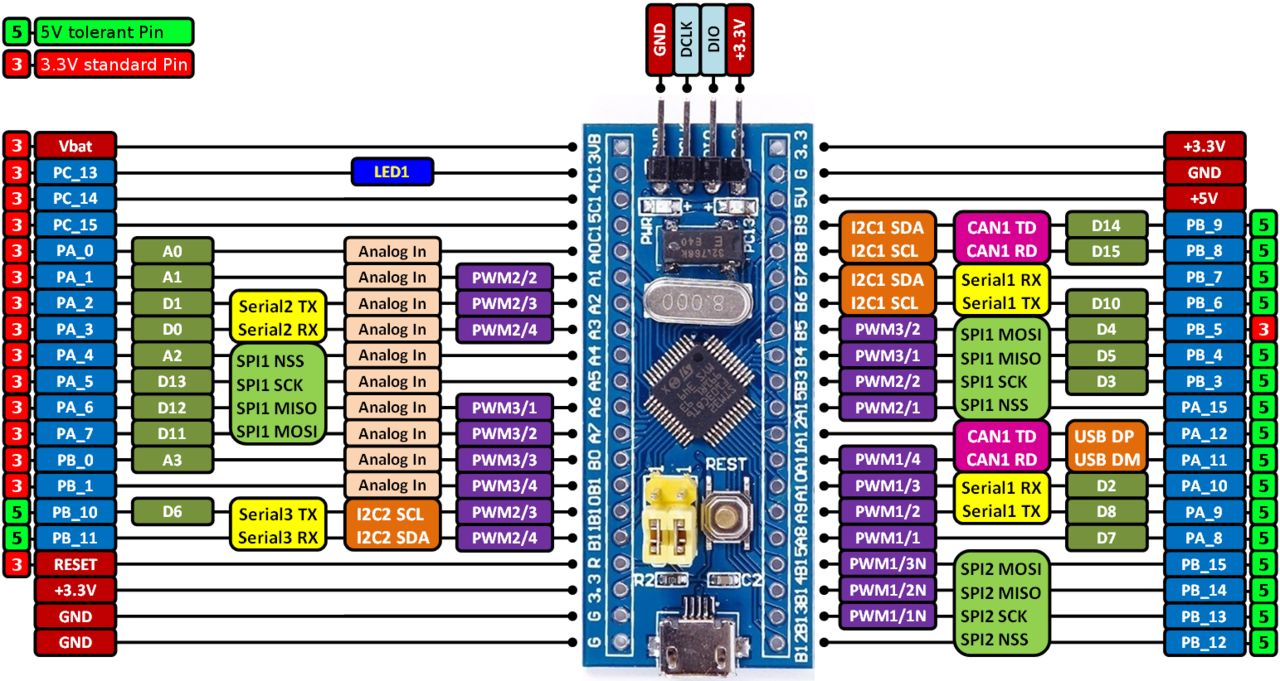
This is the pinout of the Bluepill board:


Additional example programs
Bare metal on Bluepill
Bare metal with EventQueue on Bluepill
Warning
The examples above are not meant to be compiled with the online compiler. Follow these steps to import and compile them with Mbed CLI:
mbed import Program's_URL
mbed compile -t GCC_ARM -m bluepill
Known issues
- Please check the issues reported.
TARGET_BLUEPILL/PeripheralPins.c
- Committer:
- hudakz
- Date:
- 2021-01-08
- Revision:
- 10:fc04048e7188
- Parent:
- 9:eb0ca18f5777
File content as of revision 10:fc04048e7188:
/* mbed Microcontroller Library
 *******************************************************************************
 * Copyright (c) 2018, STMicroelectronics
 * All rights reserved.
 *
 * Redistribution and use in source and binary forms, with or without
 * modification, are permitted provided that the following conditions are met:
 *
 * 1. Redistributions of source code must retain the above copyright notice,
 *    this list of conditions and the following disclaimer.
 * 2. Redistributions in binary form must reproduce the above copyright notice,
 *    this list of conditions and the following disclaimer in the documentation
 *    and/or other materials provided with the distribution.
 * 3. Neither the name of STMicroelectronics nor the names of its contributors
 *    may be used to endorse or promote products derived from this software
 *    without specific prior written permission.
 *
 * THIS SOFTWARE IS PROVIDED BY THE COPYRIGHT HOLDERS AND CONTRIBUTORS "AS IS"
 * AND ANY EXPRESS OR IMPLIED WARRANTIES, INCLUDING, BUT NOT LIMITED TO, THE
 * IMPLIED WARRANTIES OF MERCHANTABILITY AND FITNESS FOR A PARTICULAR PURPOSE ARE
 * DISCLAIMED. IN NO EVENT SHALL THE COPYRIGHT HOLDER OR CONTRIBUTORS BE LIABLE
 * FOR ANY DIRECT, INDIRECT, INCIDENTAL, SPECIAL, EXEMPLARY, OR CONSEQUENTIAL
 * DAMAGES (INCLUDING, BUT NOT LIMITED TO, PROCUREMENT OF SUBSTITUTE GOODS OR
 * SERVICES; LOSS OF USE, DATA, OR PROFITS; OR BUSINESS INTERRUPTION) HOWEVER
 * CAUSED AND ON ANY THEORY OF LIABILITY, WHETHER IN CONTRACT, STRICT LIABILITY,
 * OR TORT (INCLUDING NEGLIGENCE OR OTHERWISE) ARISING IN ANY WAY OUT OF THE USE
 * OF THIS SOFTWARE, EVEN IF ADVISED OF THE POSSIBILITY OF SUCH DAMAGE.
 *******************************************************************************
 *
 * Automatically generated from STM32F103C(8-B)Tx.xml
 */

#include "PeripheralPins.h"
#include "mbed_toolchain.h"

//==============================================================================
// Notes
//
// - The pins mentioned Px_y_ALTz are alternative possibilities which use other
//   HW peripheral instances. You can use them the same way as any other "normal"
//   pin (i.e. PwmOut pwm(PA_7_ALT0);). These pins are not displayed on the board
//   pinout image on mbed.org.
//
// - The pins which are connected to other components present on the board have
//   the comment "Connected to xxx". The pin function may not work properly in this
//   case. These pins may not be displayed on the board pinout image on mbed.org.
//   Please read the board reference manual and schematic for more information.
//
// - Warning: pins connected to the default STDIO_UART_TX and STDIO_UART_RX pins are commented
//   See https://os.mbed.com/teams/ST/wiki/STDIO for more information.
//
//==============================================================================


//*** ADC ***

MBED_WEAK const PinMap PinMap_ADC[] = {
    {PA_0, ADC_1, STM_PIN_DATA_EXT(STM_MODE_ANALOG, GPIO_NOPULL, 0, 0, 0)}, // ADC_IN0
    {PA_1, ADC_1, STM_PIN_DATA_EXT(STM_MODE_ANALOG, GPIO_NOPULL, 0, 1, 0)}, // ADC_IN1
    {PA_2, ADC_1, STM_PIN_DATA_EXT(STM_MODE_ANALOG, GPIO_NOPULL, 0, 2, 0)}, // ADC_IN2
    {PA_3, ADC_1, STM_PIN_DATA_EXT(STM_MODE_ANALOG, GPIO_NOPULL, 0, 3, 0)}, // ADC_IN3
    {PA_4, ADC_1, STM_PIN_DATA_EXT(STM_MODE_ANALOG, GPIO_NOPULL, 0, 4, 0)}, // ADC_IN4
    {PA_5, ADC_1, STM_PIN_DATA_EXT(STM_MODE_ANALOG, GPIO_NOPULL, 0, 5, 0)}, // ADC_IN5
    {PA_6, ADC_1, STM_PIN_DATA_EXT(STM_MODE_ANALOG, GPIO_NOPULL, 0, 6, 0)}, // ADC_IN6
    {PA_7, ADC_1, STM_PIN_DATA_EXT(STM_MODE_ANALOG, GPIO_NOPULL, 0, 7, 0)}, // ADC_IN7
    {PB_0, ADC_1, STM_PIN_DATA_EXT(STM_MODE_ANALOG, GPIO_NOPULL, 0, 8, 0)}, // ADC_IN8
    {PB_1, ADC_1, STM_PIN_DATA_EXT(STM_MODE_ANALOG, GPIO_NOPULL, 0, 9, 0)}, // ADC_IN9
    {PC_0, ADC_1, STM_PIN_DATA_EXT(STM_MODE_ANALOG, GPIO_NOPULL, 0, 10, 0)}, // ADC_IN10
    {PC_1, ADC_1, STM_PIN_DATA_EXT(STM_MODE_ANALOG, GPIO_NOPULL, 0, 11, 0)}, // ADC_IN11
    {PC_2, ADC_1, STM_PIN_DATA_EXT(STM_MODE_ANALOG, GPIO_NOPULL, 0, 12, 0)}, // ADC_IN12
    {PC_3, ADC_1, STM_PIN_DATA_EXT(STM_MODE_ANALOG, GPIO_NOPULL, 0, 13, 0)}, // ADC_IN13
    {PC_4, ADC_1, STM_PIN_DATA_EXT(STM_MODE_ANALOG, GPIO_NOPULL, 0, 14, 0)}, // ADC_IN14
    {PC_5, ADC_1, STM_PIN_DATA_EXT(STM_MODE_ANALOG, GPIO_NOPULL, 0, 15, 0)}, // ADC_IN15
    {NC, NC, 0}
};

const PinMap PinMap_ADC_Internal[] = {
    {ADC_TEMP, ADC_1, STM_PIN_DATA_EXT(STM_MODE_ANALOG, GPIO_NOPULL, 0, 16, 0)}, // ADC_IN16
    {ADC_VREF, ADC_1, STM_PIN_DATA_EXT(STM_MODE_ANALOG, GPIO_NOPULL, 0, 17, 0)}, // ADC_IN17
    {NC,   NC,    0}
};

//*** I2C ***

MBED_WEAK const PinMap PinMap_I2C_SDA[] = {
    {PB_7,       I2C_1, STM_PIN_DATA(STM_MODE_AF_OD, GPIO_NOPULL, 0)},
    {PB_9,       I2C_1, STM_PIN_DATA(STM_MODE_AF_OD, GPIO_NOPULL, 2)},
    {PB_11,      I2C_2, STM_PIN_DATA(STM_MODE_AF_OD, GPIO_NOPULL, 0)},
    {NC, NC, 0}
};

MBED_WEAK const PinMap PinMap_I2C_SCL[] = {
    {PB_6,       I2C_1, STM_PIN_DATA(STM_MODE_AF_OD, GPIO_NOPULL, 0)},
    {PB_8,       I2C_1, STM_PIN_DATA(STM_MODE_AF_OD, GPIO_NOPULL, 2)},
    {PB_10,      I2C_2, STM_PIN_DATA(STM_MODE_AF_OD, GPIO_NOPULL, 0)},
    {NC, NC, 0}
};

//*** PWM ***

// TIM4 cannot be used because already used by the us_ticker
// You have to comment all PWM_4
MBED_WEAK const PinMap PinMap_PWM[] = {
    {PA_0,       PWM_2,  STM_PIN_DATA_EXT(STM_MODE_AF_PP, GPIO_PULLUP, 0, 1, 0)}, // TIM2_CH1
    {PA_1,       PWM_2,  STM_PIN_DATA_EXT(STM_MODE_AF_PP, GPIO_PULLUP, 0, 2, 0)}, // TIM2_CH2
    {PA_2,       PWM_2,  STM_PIN_DATA_EXT(STM_MODE_AF_PP, GPIO_PULLUP, 0, 3, 0)}, // TIM2_CH3
    {PA_3,       PWM_2,  STM_PIN_DATA_EXT(STM_MODE_AF_PP, GPIO_PULLUP, 0, 4, 0)}, // TIM2_CH4
    {PA_6,       PWM_3,  STM_PIN_DATA_EXT(STM_MODE_AF_PP, GPIO_PULLUP, 0, 1, 0)}, // TIM3_CH1
    {PA_7,       PWM_3,  STM_PIN_DATA_EXT(STM_MODE_AF_PP, GPIO_PULLUP, 0, 2, 0)}, // TIM3_CH2
    {PA_8,       PWM_1,  STM_PIN_DATA_EXT(STM_MODE_AF_PP, GPIO_PULLUP, 0, 1, 0)}, // TIM1_CH1
    {PA_8,       PWM_1,  STM_PIN_DATA_EXT(STM_MODE_AF_PP, GPIO_PULLUP, 6, 1, 0)}, // TIM1_CH1
    {PA_9,       PWM_1,  STM_PIN_DATA_EXT(STM_MODE_AF_PP, GPIO_PULLUP, 0, 2, 0)}, // TIM1_CH2
    {PA_9,       PWM_1,  STM_PIN_DATA_EXT(STM_MODE_AF_PP, GPIO_PULLUP, 6, 2, 0)}, // TIM1_CH2
    {PA_10,      PWM_1,  STM_PIN_DATA_EXT(STM_MODE_AF_PP, GPIO_PULLUP, 0, 3, 0)}, // TIM1_CH3
    {PA_10,      PWM_1,  STM_PIN_DATA_EXT(STM_MODE_AF_PP, GPIO_PULLUP, 6, 3, 0)}, // TIM1_CH3
    {PA_11,      PWM_1,  STM_PIN_DATA_EXT(STM_MODE_AF_PP, GPIO_PULLUP, 0, 4, 0)}, // TIM1_CH4
    {PA_11,      PWM_1,  STM_PIN_DATA_EXT(STM_MODE_AF_PP, GPIO_PULLUP, 6, 4, 0)}, // TIM1_CH4
    {PA_15,      PWM_2,  STM_PIN_DATA_EXT(STM_MODE_AF_PP, GPIO_PULLUP, 8, 1, 0)}, // TIM2_CH1
    {PB_0,       PWM_1,  STM_PIN_DATA_EXT(STM_MODE_AF_PP, GPIO_PULLUP, 6, 2, 1)}, // TIM1_CH2N
    {PB_0_ALT0,  PWM_3,  STM_PIN_DATA_EXT(STM_MODE_AF_PP, GPIO_PULLUP, 0, 3, 0)}, // TIM3_CH3
    {PB_0_ALT0,  PWM_3,  STM_PIN_DATA_EXT(STM_MODE_AF_PP, GPIO_PULLUP, 7, 3, 0)}, // TIM3_CH3
    {PB_1,       PWM_1,  STM_PIN_DATA_EXT(STM_MODE_AF_PP, GPIO_PULLUP, 6, 3, 1)}, // TIM1_CH3N
    {PB_1_ALT0,  PWM_3,  STM_PIN_DATA_EXT(STM_MODE_AF_PP, GPIO_PULLUP, 0, 4, 0)}, // TIM3_CH4
    {PB_1_ALT0,  PWM_3,  STM_PIN_DATA_EXT(STM_MODE_AF_PP, GPIO_PULLUP, 7, 4, 0)}, // TIM3_CH4
    {PB_3,       PWM_2,  STM_PIN_DATA_EXT(STM_MODE_AF_PP, GPIO_PULLUP, 8, 2, 0)}, // TIM2_CH2
    {PB_4,       PWM_3,  STM_PIN_DATA_EXT(STM_MODE_AF_PP, GPIO_PULLUP, 7, 1, 0)}, // TIM3_CH1
    {PB_5,       PWM_3,  STM_PIN_DATA_EXT(STM_MODE_AF_PP, GPIO_PULLUP, 7, 2, 0)}, // TIM3_CH2
//  {PB_6,       PWM_4,  STM_PIN_DATA_EXT(STM_MODE_AF_PP, GPIO_PULLUP, 0, 1, 0)}, // TIM4_CH1
//  {PB_7,       PWM_4,  STM_PIN_DATA_EXT(STM_MODE_AF_PP, GPIO_PULLUP, 0, 2, 0)}, // TIM4_CH2
//  {PB_8,       PWM_4,  STM_PIN_DATA_EXT(STM_MODE_AF_PP, GPIO_PULLUP, 0, 3, 0)}, // TIM4_CH3
//  {PB_9,       PWM_4,  STM_PIN_DATA_EXT(STM_MODE_AF_PP, GPIO_PULLUP, 0, 4, 0)}, // TIM4_CH4
    {PB_10,      PWM_2,  STM_PIN_DATA_EXT(STM_MODE_AF_PP, GPIO_PULLUP, 8, 3, 0)}, // TIM2_CH3
    {PB_11,      PWM_2,  STM_PIN_DATA_EXT(STM_MODE_AF_PP, GPIO_PULLUP, 8, 4, 0)}, // TIM2_CH4
    {PB_13,      PWM_1,  STM_PIN_DATA_EXT(STM_MODE_AF_PP, GPIO_PULLUP, 0, 1, 1)}, // TIM1_CH1N
    {PB_14,      PWM_1,  STM_PIN_DATA_EXT(STM_MODE_AF_PP, GPIO_PULLUP, 0, 2, 1)}, // TIM1_CH2N
    {PB_15,      PWM_1,  STM_PIN_DATA_EXT(STM_MODE_AF_PP, GPIO_PULLUP, 0, 3, 1)}, // TIM1_CH3N
    {NC, NC, 0}
};

//*** SERIAL ***

MBED_WEAK const PinMap PinMap_UART_TX[] = {
    {PA_2,       UART_2,  STM_PIN_DATA(STM_MODE_AF_PP, GPIO_PULLUP, 0)},
    {PA_9,       UART_1,  STM_PIN_DATA(STM_MODE_AF_PP, GPIO_PULLUP, 0)},
    {PB_6,       UART_1,  STM_PIN_DATA(STM_MODE_AF_PP, GPIO_PULLUP, 3)}, // GPIO_Remap_USART1
    {PB_10,      UART_3,  STM_PIN_DATA(STM_MODE_AF_PP, GPIO_PULLUP, 0)},
    {PC_10,      UART_3,  STM_PIN_DATA(STM_MODE_AF_PP, GPIO_PULLUP, 5)}, // GPIO_PartialRemap_USART3
    {NC, NC, 0}
};

MBED_WEAK const PinMap PinMap_UART_RX[] = {
    {PA_3,       UART_2,  STM_PIN_DATA(STM_MODE_INPUT, GPIO_PULLUP, 0)},
    {PA_10,      UART_1,  STM_PIN_DATA(STM_MODE_INPUT, GPIO_PULLUP, 0)},
    {PB_7,       UART_1,  STM_PIN_DATA(STM_MODE_INPUT, GPIO_PULLUP, 3)}, // GPIO_Remap_USART1
    {PB_11,      UART_3,  STM_PIN_DATA(STM_MODE_INPUT, GPIO_PULLUP, 0)},
    {PC_11,      UART_3,  STM_PIN_DATA(STM_MODE_INPUT, GPIO_PULLUP, 5)}, // GPIO_PartialRemap_USART3
    {NC, NC, 0}
};

MBED_WEAK const PinMap PinMap_UART_RTS[] = {
    {PA_1,       UART_2,  STM_PIN_DATA(STM_MODE_AF_PP, GPIO_PULLUP, 0)},
    {PA_12,      UART_1,  STM_PIN_DATA(STM_MODE_AF_PP, GPIO_PULLUP, 0)},
    {PB_14,      UART_3,  STM_PIN_DATA(STM_MODE_AF_PP, GPIO_PULLUP, 0)},
    {NC, NC, 0}
};

MBED_WEAK const PinMap PinMap_UART_CTS[] = {
    {PA_0,       UART_2,  STM_PIN_DATA(STM_MODE_AF_PP, GPIO_PULLUP, 0)},
    {PA_11,      UART_1,  STM_PIN_DATA(STM_MODE_AF_PP, GPIO_PULLUP, 0)},
    {PB_13,      UART_3,  STM_PIN_DATA(STM_MODE_AF_PP, GPIO_PULLUP, 0)},
    {NC, NC, 0}
};

//*** SPI ***

MBED_WEAK const PinMap PinMap_SPI_MOSI[] = {
    {PA_7,       SPI_1, STM_PIN_DATA(STM_MODE_AF_PP, GPIO_NOPULL, 0)},
    {PB_5,       SPI_1, STM_PIN_DATA(STM_MODE_AF_PP, GPIO_NOPULL, 1)},
    {PB_15,      SPI_2, STM_PIN_DATA(STM_MODE_AF_PP, GPIO_NOPULL, 0)},
    {NC, NC, 0}
};

MBED_WEAK const PinMap PinMap_SPI_MISO[] = {
    {PA_6,       SPI_1, STM_PIN_DATA(STM_MODE_AF_PP, GPIO_NOPULL, 0)},
    {PB_4,       SPI_1, STM_PIN_DATA(STM_MODE_AF_PP, GPIO_NOPULL, 1)},
    {PB_14,      SPI_2, STM_PIN_DATA(STM_MODE_AF_PP, GPIO_NOPULL, 0)},
    {NC, NC, 0}
};

MBED_WEAK const PinMap PinMap_SPI_SCLK[] = {
    {PA_5,       SPI_1, STM_PIN_DATA(STM_MODE_AF_PP, GPIO_NOPULL, 0)},
    {PB_3,       SPI_1, STM_PIN_DATA(STM_MODE_AF_PP, GPIO_NOPULL, 1)},
    {PB_13,      SPI_2, STM_PIN_DATA(STM_MODE_AF_PP, GPIO_NOPULL, 0)},
    {NC, NC, 0}
};

MBED_WEAK const PinMap PinMap_SPI_SSEL[] = {
    {PA_4,       SPI_1, STM_PIN_DATA(STM_MODE_AF_PP, GPIO_NOPULL, 0)},
    {PA_15,      SPI_1, STM_PIN_DATA(STM_MODE_AF_PP, GPIO_NOPULL, 1)},
    {PB_12,      SPI_2, STM_PIN_DATA(STM_MODE_AF_PP, GPIO_NOPULL, 0)},
    {NC, NC, 0}
};

//*** CAN ***

MBED_WEAK const PinMap PinMap_CAN_RD[] = {
    {PA_11,      CAN_1, STM_PIN_DATA(STM_MODE_INPUT, GPIO_NOPULL, 0)},
    {PB_8,       CAN_1, STM_PIN_DATA(STM_MODE_INPUT, GPIO_NOPULL, 10)},
    {NC, NC, 0}
};

MBED_WEAK const PinMap PinMap_CAN_TD[] = {
    {PA_12,      CAN_1, STM_PIN_DATA(STM_MODE_AF_PP, GPIO_NOPULL, 0)},
    {PB_9,       CAN_1, STM_PIN_DATA(STM_MODE_AF_PP, GPIO_NOPULL, 10)},
    {NC, NC, 0}
};

//*** USBDEVICE ***

MBED_WEAK const PinMap PinMap_USB_FS[] = {
    {PA_11,     USB_FS, STM_PIN_DATA(STM_MODE_INPUT, GPIO_NOPULL, 0)}, // USB_DM
    {PA_12,     USB_FS, STM_PIN_DATA(STM_MODE_INPUT, GPIO_NOPULL, 0)}, // USB_DP
    {NC, NC, 0}
};