Dual CANbus monitor and instrumentation cluster
Eagle Schematic and Board design
/media/uploads/TickTock/canaryr5.zip
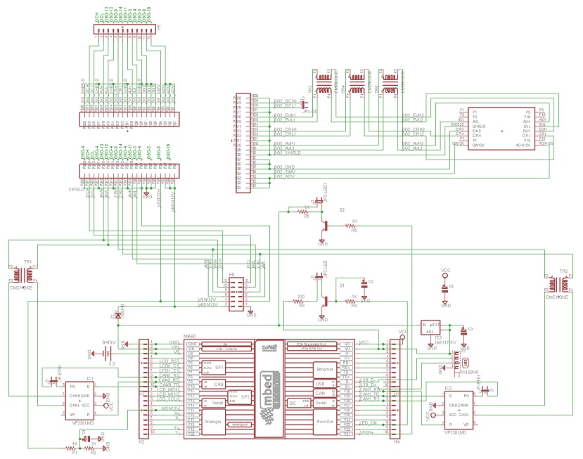
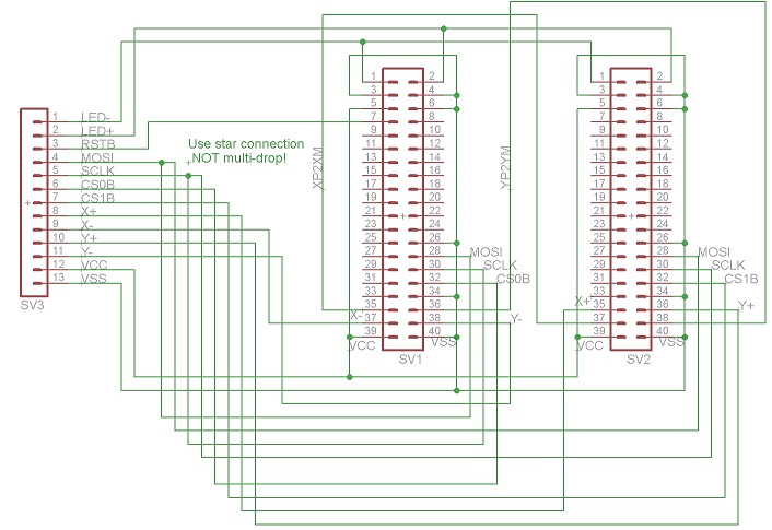
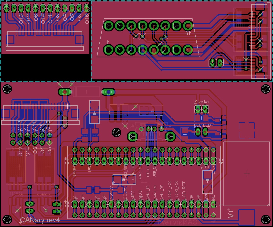
Parts List
Assembly
1) LCD Displays
I found ribbon cable is a nice way to organize the wires to the displays. You'll need 12 conductors and I connected them in the following order:
| 1 | LED+ |
| 2 | LED- |
| 3 | RSTB |
| 4 | MOSI |
| 5 | SCLK |
| 6 | CSB |
| 7 | X+ |
| 8 | X- |
| 9 | Y+ |
| 10 | Y- |
| 11 | VDD |
| 12 | GND |
First I connected all the GND connections (IM0, IM1, IM3, & 2 GND). Do not connect the bottom GND until you have the ribbon cable connected. After making all the ribbon cable connections (connecting the GND of the ribbon cable to the bottom GND pad), solder the GND bar from the previous step to the back of the bottom GND connection. Finally, make a connection from the back side 3.3V pin to IM2. Take a break and repeat for the second display.
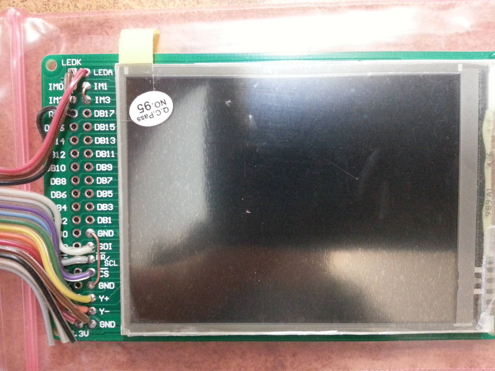
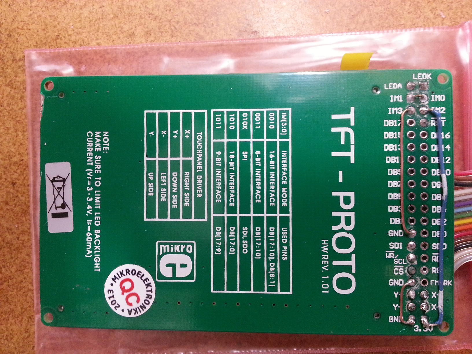 Once the two displays are complete combine all wires except CS0, CS1, X+, X-, Y+, and Y-. Connect X- of the left display to X+ of the right. Similarly connect Y- of the left display to Y+ of the right. Insulate any exposed wires.
2) PCB
Refer to the schematics to place all the components on the board. If you plan to install into the CANary 3D enclosure, DO NOT install the battery holder or the socket for the mbed and, instead, connect two wires to the VB and GND pads nearby. You will have to install the battery holder against the back wall to avoid interfering with the right-hand display and the mbed will have to be directly soldered. I have not found a socket with a low enough profile to fit in the space provided (depth of enclosure is limited by the space behind the center console). Also, I recommend keeping as much lead as possible on the Zener diode (bending it as shown to clear the back wall). Although it is operating well within parameters, the Zener gets quite hot during extended operation and the leads help dissipate the heat and keep it away from the PCB and other components.
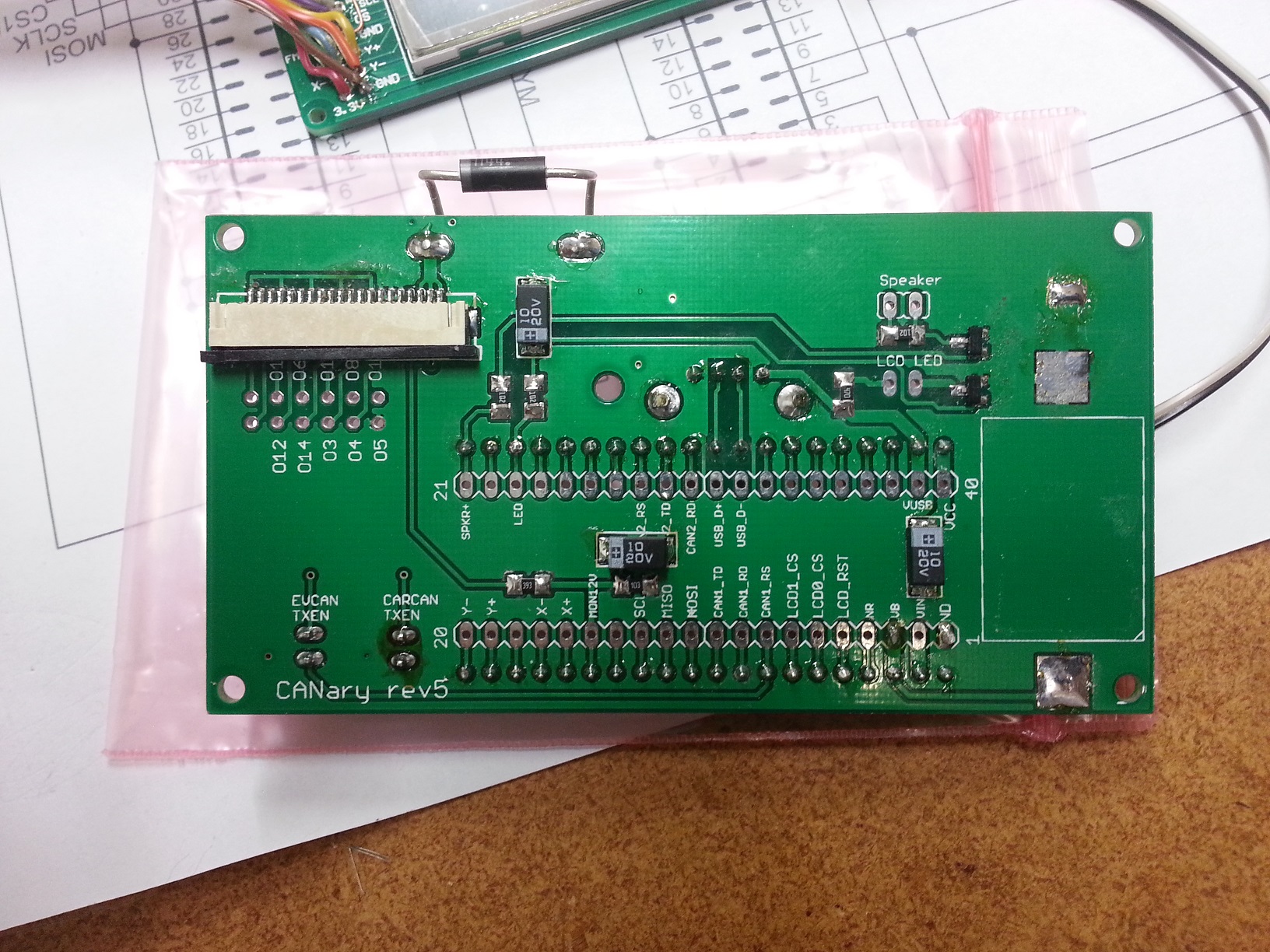
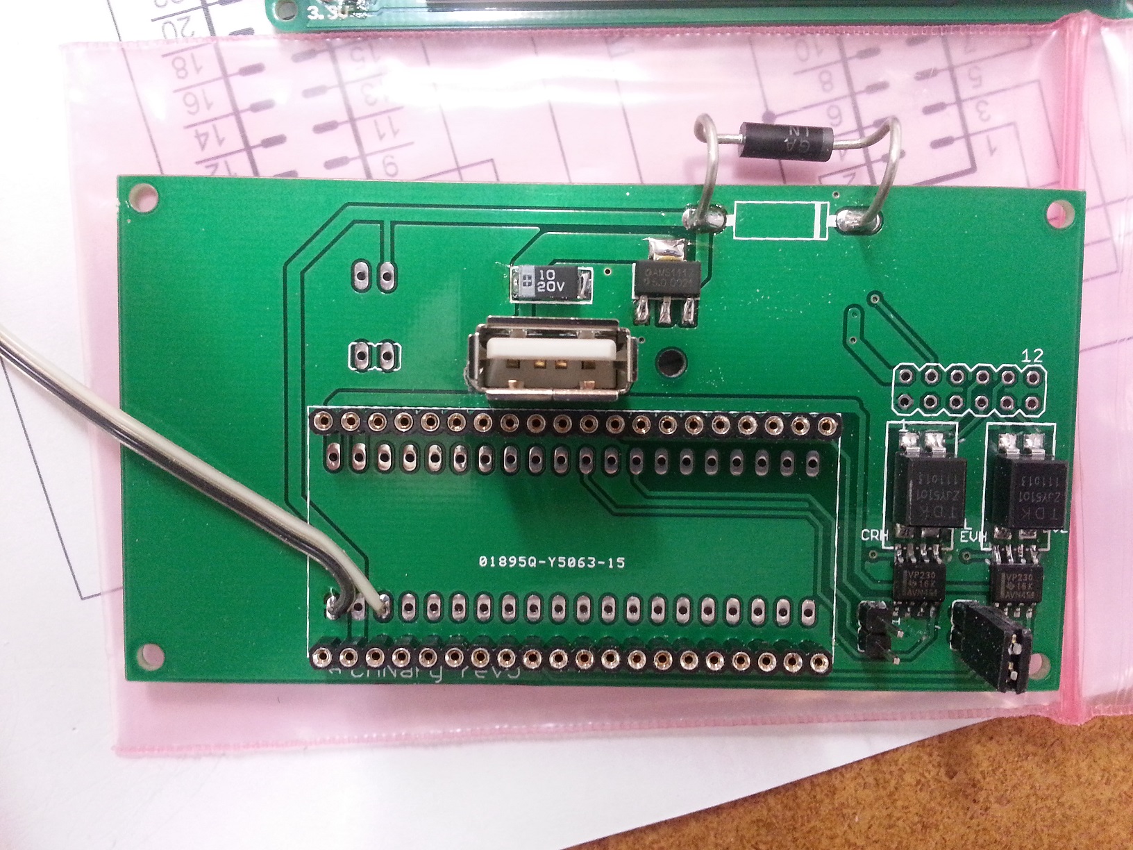
Once the PCB is populated, solder the LCDs to the PCB. CS0 connects to the right display and CS1 connects to the left.
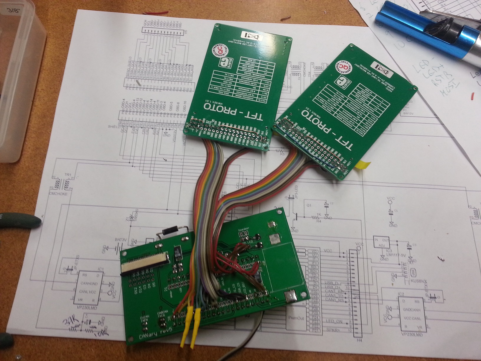
3) Testing
| 1) | First step is to buzz out all connections from the LCDs to the pins in the main board |
| 2) | Next check the touch screen connections. On the main board, place an Ohm meter across X+ and X-. You should read 700 Ohms. Repeat for Y+ and Y-. Then test the resistance from X+ to Y+. With nothing touching the screens, it should read >100K Ohms and <1K when touching either screen. |
| 3) | When all connections are checked, solder in the mbed. Download and install the touch2 program http://mbed.org/users/TickTock/code/touch2/ to test the basic operation of the mbed and touch screens. |
| tips: | |
| Touch screen is sensitive - excess flux on X+,X-,Y+,Y- connection on mbed can result in flakey operation | |
| If touch is not working, double-check the LCD0_CS and LCD1_CS are not swapped. LCD0_CS must connect to the CS of the LCD that has X- & Y- connected to the mbed. LCD1_CS must connect to the CS of the LCD that has X+ & Y+ connected to the mbed. | |
| 4) | Once touch2 works, it is time to connect to the OBD connector. I highly recommend double checking all connections from the OBD to the PCB with the cable in place before connecting to the Leaf. Buzz out all the pins in the OBS to make sure none are shorting to each other, Check that the 12V goes to the Zener (and nothing else) and the switched 12V to the resistor divider (and nothing else). Test the ground connection properly connects to ground and nothing else. |
| 5) | Once you are confident there are no shorts or wrong connections from the OBD connector, take a deep breath and plug it into your leaf. Touch2 program should come up and function. Unplug and install the latest CANary firmware. Test all features before installing into the enclosure (gids, cellpair, menu system, logging) since installing and removing from the enclosure is a PITA. |
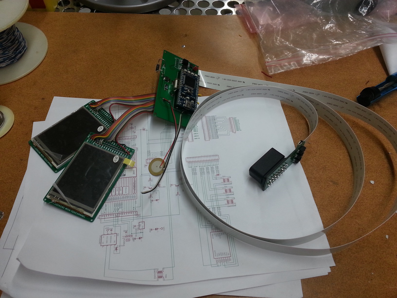
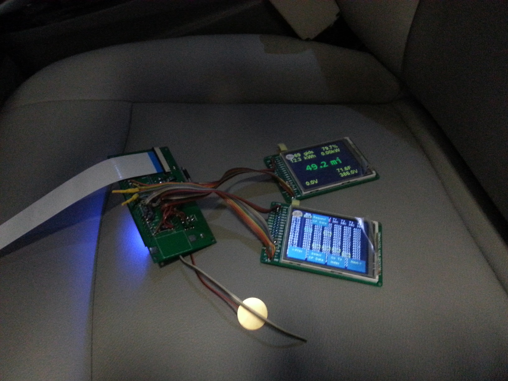
4) Enclosure
The 3D printer leaves a lot of powder behind - I used a strong spray of water to get it out of all the cracks. The enclosure comes with a rather rough finish. I recommend convincing yourself you like it, then simply lightly sand then paint before assembly. Sanding is very difficult - the nylon is very nicely fused and doesn't want to sand. I tried sandblasting and that didn't work either. I had some limited success with filler and then sanding, but only on the outside - it is too difficult to sand the face.
5) Final Assembly
Util/stringUtils.h
- Committer:
- TickTock
- Date:
- 2013-02-03
- Revision:
- 1:9dcd70c32180
File content as of revision 1:9dcd70c32180:
/*
Copyright (c) 2011 Robert Ellis (holistic [at] robellis [dot] org [dot] uk)

Permission is hereby granted, free of charge, to any person obtaining a copy
of this software and associated documentation files (the "Software"), to deal
in the Software without restriction, including without limitation the rights
to use, copy, modify, merge, publish, distribute, sublicense, and/or sell
copies of the Software, and to permit persons to whom the Software is
furnished to do so, subject to the following conditions:

The above copyright notice and this permission notice shall be included in
all copies or substantial portions of the Software.

THE SOFTWARE IS PROVIDED "AS IS", WITHOUT WARRANTY OF ANY KIND, EXPRESS OR
IMPLIED, INCLUDING BUT NOT LIMITED TO THE WARRANTIES OF MERCHANTABILITY,
FITNESS FOR A PARTICULAR PURPOSE AND NONINFRINGEMENT. IN NO EVENT SHALL THE
AUTHORS OR COPYRIGHT HOLDERS BE LIABLE FOR ANY CLAIM, DAMAGES OR OTHER
LIABILITY, WHETHER IN AN ACTION OF CONTRACT, TORT OR OTHERWISE, ARISING FROM,
OUT OF OR IN CONNECTION WITH THE SOFTWARE OR THE USE OR OTHER DEALINGS IN
THE SOFTWARE.
*/

#ifndef STRING_UTILS_H
#define STRING_UTILS_H

#include <string>
#include <vector>
using namespace std;

/**
 * Trims whitespace characters from beginning and end of given string.
 */
string trim(const string& src, const string& c = " \r\n");

/**
 * Tokenize given string delimmted by given delimter into a vector of seprate strings.
 */
vector<string> tokenize(const string& str, const string& delimiters = " ");

#endif

