Important changes to repositories hosted on mbed.com
Mbed hosted mercurial repositories are deprecated and are due to be permanently deleted in July 2026.
To keep a copy of this software download the repository Zip archive or clone locally using Mercurial.
It is also possible to export all your personal repositories from the account settings page.
DEPRECATED
This example application is not maintained and not recommended. It uses an old version of Mbed OS, Pelion DM and Arm toolchain. It doesn't work with Mbed Studio.
Please use: https://os.mbed.com/teams/mbed-os-examples/code/mbed-os-example-pelion/
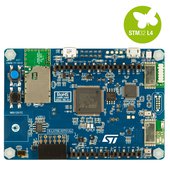
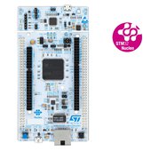
This example is known to work great on the following platforms:
- DISCO_L475E_IOT01A - onboard WiFI and onboard QSPI flash. Board specific example using onboard sensors is available here.
- DISCO_F413H - onboard WiFI and onboard QSPI flash.
- DISCO_F469NI - WizFi310 WiFI shield and onboard QSPI flash (see WiFi shield instructions).
- DISCO_F746NG - onboard Ethernet and using onboard QSPI flash.
- DISCO_F769NI - onboard Ethernet and using onboard QSPI flash.
- DISCO_L496AG - WizFi310 WiFI shield and onboard QSPI flash (see WiFi shield instructions).
- NUCLEO_F207ZG - onboard Ethernet and wired SD card (SD card wiring instructions).
- NUCLEO_F412ZG - WizFi310 WiFI shield and SD card shield (see WiFi shield instructions).
- NUCLEO_F429ZI - onboard Ethernet and wired SD card (SD card wiring instructions).
- NUCLEO_F746ZG - onboard Ethernet and wired SD card (SD card wiring instructions).
- NUCLEO_F767ZI - onboard Ethernet and wired SD card (SD card wiring instructions).
- NUCLEO_L476RG - WizFi310 WiFI shield and SD card shield (see WiFi shield instructions).
- NUCLEO_L496ZG - WizFi310 WiFI shield and SD card shield (see WiFi shield instructions).
- NUCLEO_L4R5ZI - WizFi310 WiFI shield and SD card shield (see WiFi shield instructions).
Follow the Quick-Start instructions: https://cloud.mbed.com/quick-start

Example functionality
This example showcases the following device functionality:
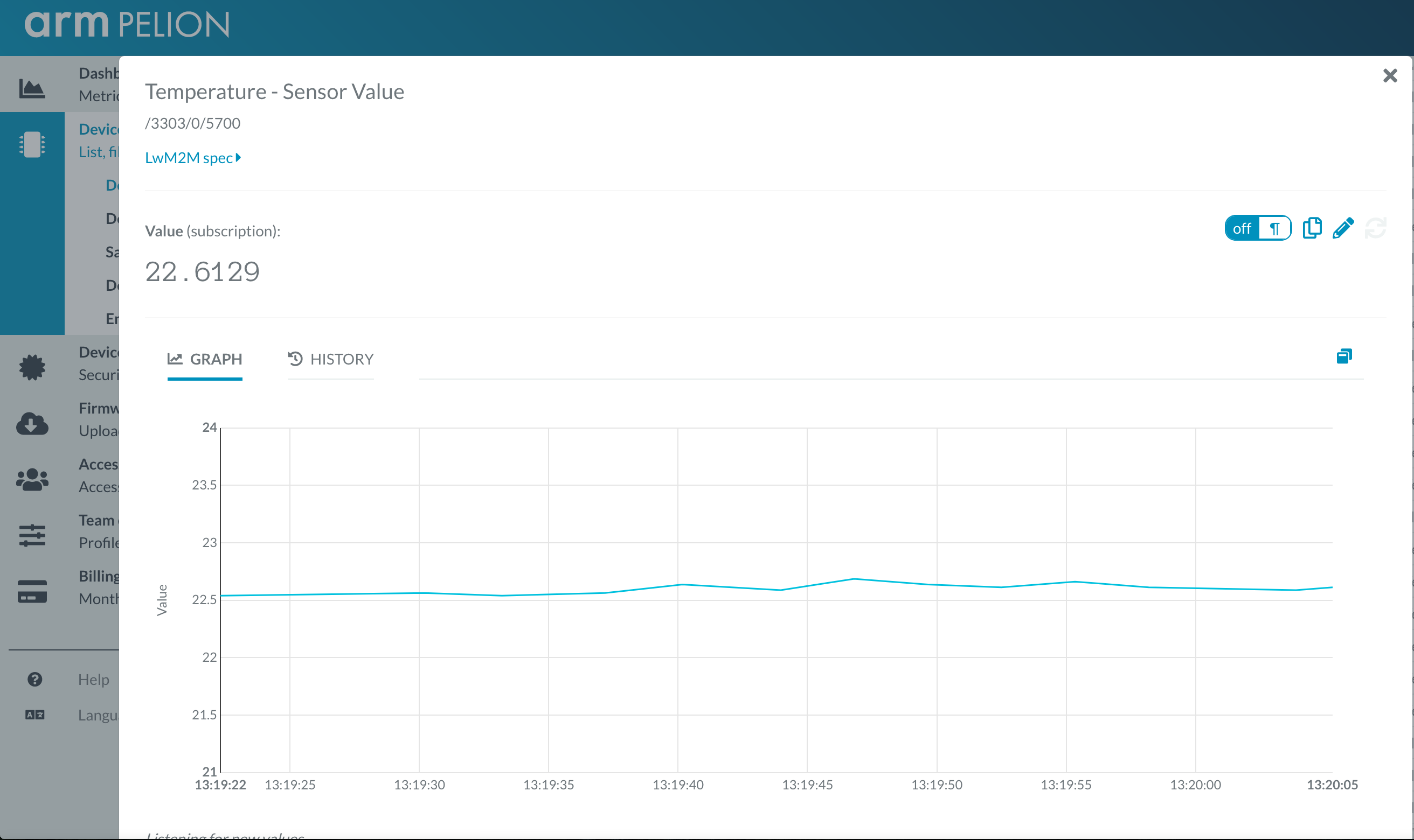
- Read ADC temperature and ADC vref, and report them as Pelion LWM2M resources (see image below).
- On user button click, increment Pelion LWM2M button resource.
- Allow the user to change the state of the board LED from Pelion LWM2M led_state resource and PUT request.
SD card wiring
The ST Nucleo family of boards don't have storage onboard and therefore you will need an SD card. A limitation on ST Nucleo 144 boards is that there's a conflict between Ethernet and SPI pins on Arduino D11. Due to this, the SD card must be wired to different SPI bus that doesn't conflict with other functionality. The image below provide instructions on how to wire an SD card to a non-conflicting SPI instance.
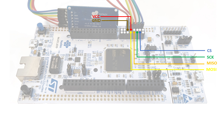
If you are not a first-time Pelion Device Management user your device's SD card may already have connect and update certificates on it. If this is the case, remove and manually format your micro SD card, flash the binary to the device and then re-insert your micro SD card.
WiFi shield setup/wiring
Some ST Nucleo and Discovery boards don't have IP connectivity option, but bundled with a WiFi shield, they can take benefit of full device management capabilities. See links to reference images below on how to wire WizFI310 WiFi shield and/or SD card shield:
- ST DISCO_F469NI + WizFi310 WiFi Shield
- ST DISCO_L496AG + WizFi310 WiFi Shield
- ST NUCLEO_F412ZG + WizFi310 WiFi Shield + SD card shield
- ST NUCLEO_L476RG + WizFi310 WiFi Shield + SD card shield
- ST NUCLEO_L496ZG + WizFi310 WiFi Shield + SD card shield
- ST NUCLEO_L4R5ZI + WizFi310 WiFi Shield + SD card shield
Use this example with Mbed CLI
1. Import the application into your desktop:
mbed import /teams/ST/code/pelion-example-common

cd pelion-example-common
2. Install the CLOUD_SDK_API_KEY
mbed config -G CLOUD_SDK_API_KEY <PELION_DM_API_KEY>
For instructions on how to generate your API key, please see the documentation.
3. Initialize firmware credentials (done once per repository). You can use the following command:
mbed dm init -d "<your company name in Pelion DM>" --model-name "<product model identifier>" -q --force
If above command do not work for your Mbed CLI, please consider upgrading Mbed CLI to version 1.8.x or above.
4. Compile and program:
mbed compile -t <toolchain> -m <TARGET_BOARD>
(supported toolchains : GCC_ARM / ARM / IAR)
targets/TARGET_STM32L475xG_SRAM2/TARGET_MTB_STM_L475/PinNames.h
- Committer:
- screamer
- Date:
- 2019-03-21
- Revision:
- 23:64f3f756acf6
File content as of revision 23:64f3f756acf6:
/* mbed Microcontroller Library

* SPDX-License-Identifier: BSD-3-Clause
 *******************************************************************************
 * Copyright (c) 2018, STMicroelectronics
 * All rights reserved.
 *
 * Redistribution and use in source and binary forms, with or without
 * modification, are permitted provided that the following conditions are met:
 *
 * 1. Redistributions of source code must retain the above copyright notice,
 *    this list of conditions and the following disclaimer.
 * 2. Redistributions in binary form must reproduce the above copyright notice,
 *    this list of conditions and the following disclaimer in the documentation
 *    and/or other materials provided with the distribution.
 * 3. Neither the name of STMicroelectronics nor the names of its contributors
 *    may be used to endorse or promote products derived from this software
 *    without specific prior written permission.
 *
 * THIS SOFTWARE IS PROVIDED BY THE COPYRIGHT HOLDERS AND CONTRIBUTORS "AS IS"
 * AND ANY EXPRESS OR IMPLIED WARRANTIES, INCLUDING, BUT NOT LIMITED TO, THE
 * IMPLIED WARRANTIES OF MERCHANTABILITY AND FITNESS FOR A PARTICULAR PURPOSE ARE
 * DISCLAIMED. IN NO EVENT SHALL THE COPYRIGHT HOLDER OR CONTRIBUTORS BE LIABLE
 * FOR ANY DIRECT, INDIRECT, INCIDENTAL, SPECIAL, EXEMPLARY, OR CONSEQUENTIAL
 * DAMAGES (INCLUDING, BUT NOT LIMITED TO, PROCUREMENT OF SUBSTITUTE GOODS OR
 * SERVICES; LOSS OF USE, DATA, OR PROFITS; OR BUSINESS INTERRUPTION) HOWEVER
 * CAUSED AND ON ANY THEORY OF LIABILITY, WHETHER IN CONTRACT, STRICT LIABILITY,
 * OR TORT (INCLUDING NEGLIGENCE OR OTHERWISE) ARISING IN ANY WAY OUT OF THE USE
 * OF THIS SOFTWARE, EVEN IF ADVISED OF THE POSSIBILITY OF SUCH DAMAGE.
 *******************************************************************************
 */

#ifndef MBED_PINNAMES_H
#define MBED_PINNAMES_H

#include "cmsis.h"
#include "PinNamesTypes.h"

#ifdef __cplusplus
extern "C" {
#endif

typedef enum {
    ALT0  = 0x100,
    ALT1  = 0x200,
    ALT2  = 0x300,
    ALT3  = 0x400
} ALTx;

typedef enum {
    PA_0  = 0x00,
    PA_0_ALT0 = PA_0 | ALT0,
    PA_1  = 0x01,
    PA_1_ALT0 = PA_1 | ALT0,
    PA_2  = 0x02,
    PA_2_ALT0 = PA_2 | ALT0,
    PA_3  = 0x03,
    PA_3_ALT0 = PA_3 | ALT0,
    PA_4  = 0x04,
    PA_4_ALT0 = PA_4 | ALT0,
    PA_5  = 0x05,
    PA_5_ALT0 = PA_5 | ALT0,
    PA_6  = 0x06,
    PA_6_ALT0 = PA_6 | ALT0,
    PA_7  = 0x07,
    PA_7_ALT0 = PA_7 | ALT0,
    PA_7_ALT1 = PA_7 | ALT1,
    PA_7_ALT2 = PA_7 | ALT2,
    PA_8  = 0x08,
    PA_9  = 0x09,
    PA_10 = 0x0A,
    PA_11 = 0x0B,
    PA_12 = 0x0C,
    PA_13 = 0x0D,
    PA_14 = 0x0E,
    PA_15 = 0x0F,
    PA_15_ALT0 = PA_15 | ALT0,

    PB_0  = 0x10,
    PB_0_ALT0 = PB_0 | ALT0,
    PB_0_ALT1 = PB_0 | ALT1,
    PB_1  = 0x11,
    PB_1_ALT0 = PB_1 | ALT0,
    PB_1_ALT1 = PB_1 | ALT1,
    PB_2  = 0x12,
    PB_3  = 0x13,
    PB_3_ALT0 = PB_3 | ALT0,
    PB_4  = 0x14,
    PB_4_ALT0 = PB_4 | ALT0,
    PB_5  = 0x15,
    PB_5_ALT0 = PB_5 | ALT0,
    PB_6  = 0x16,
    PB_6_ALT0 = PB_6 | ALT0,
    PB_7  = 0x17,
    PB_7_ALT0 = PB_7 | ALT0,
    PB_8  = 0x18,
    PB_8_ALT0 = PB_8 | ALT0,
    PB_9  = 0x19,
    PB_9_ALT0 = PB_9 | ALT0,
    PB_10 = 0x1A,
    PB_11 = 0x1B,
    PB_12 = 0x1C,
    PB_13 = 0x1D,
    PB_13_ALT0 = PB_13 | ALT0,
    PB_14 = 0x1E,
    PB_14_ALT0 = PB_14 | ALT0,
    PB_14_ALT1 = PB_14 | ALT1,
    PB_15 = 0x1F,
    PB_15_ALT0 = PB_15 | ALT0,
    PB_15_ALT1 = PB_15 | ALT1,

    PC_0  = 0x20,
    PC_0_ALT0 = PC_0 | ALT0,
    PC_0_ALT1 = PC_0 | ALT1,
    PC_1  = 0x21,
    PC_1_ALT0 = PC_1 | ALT0,
    PC_1_ALT1 = PC_1 | ALT1,
    PC_2  = 0x22,
    PC_2_ALT0 = PC_2 | ALT0,
    PC_2_ALT1 = PC_2 | ALT1,
    PC_3  = 0x23,
    PC_3_ALT0 = PC_3 | ALT0,
    PC_3_ALT1 = PC_3 | ALT1,
    PC_4  = 0x24,
    PC_4_ALT0 = PC_4 | ALT0,
    PC_5  = 0x25,
    PC_5_ALT0 = PC_5 | ALT0,
    PC_6  = 0x26,
    PC_6_ALT0 = PC_6 | ALT0,
    PC_7  = 0x27,
    PC_7_ALT0 = PC_7 | ALT0,
    PC_8  = 0x28,
    PC_8_ALT0 = PC_8 | ALT0,
    PC_9  = 0x29,
    PC_9_ALT0 = PC_9 | ALT0,
    PC_10 = 0x2A,
    PC_10_ALT0 = PC_10 | ALT0,
    PC_11 = 0x2B,
    PC_11_ALT0 = PC_11 | ALT0,
    PC_12 = 0x2C,
    PC_13 = 0x2D,
    PC_14 = 0x2E,
    PC_15 = 0x2F,

    PD_0  = 0x30,
    PD_1  = 0x31,
    PD_2  = 0x32,
    PD_3  = 0x33,
    PD_4  = 0x34,
    PD_5  = 0x35,
    PD_6  = 0x36,
    PD_7  = 0x37,
    PD_8  = 0x38,
    PD_9  = 0x39,
    PD_10 = 0x3A,
    PD_11 = 0x3B,
    PD_12 = 0x3C,
    PD_13 = 0x3D,
    PD_14 = 0x3E,
    PD_15 = 0x3F,

    PE_0  = 0x40,
    PE_1  = 0x41,
    PE_2  = 0x42,
    PE_3  = 0x43,
    PE_4  = 0x44,
    PE_5  = 0x45,
    PE_6  = 0x46,
    PE_7  = 0x47,
    PE_8  = 0x48,
    PE_9  = 0x49,
    PE_10 = 0x4A,
    PE_11 = 0x4B,
    PE_12 = 0x4C,
    PE_13 = 0x4D,
    PE_14 = 0x4E,
    PE_15 = 0x4F,

    PH_0  = 0x70,
    PH_1  = 0x71,

    // ADC internal channels
    ADC_TEMP = 0xF0,
    ADC_VREF = 0xF1,
    ADC_VBAT = 0xF2,

    // Not connected
    NC = (int)0xFFFFFFFF,

    // STDIO for console print
#ifdef MBED_CONF_TARGET_STDIO_UART_TX
    STDIO_UART_TX = MBED_CONF_TARGET_STDIO_UART_TX,
#else
    STDIO_UART_TX = PA_9,
#endif
#ifdef MBED_CONF_TARGET_STDIO_UART_RX
    STDIO_UART_RX = MBED_CONF_TARGET_STDIO_UART_RX,
#else
    STDIO_UART_RX = PA_10,
#endif

    // Generic signals namings
    LED1        = PE_2, // Red LED (LD1)
    LED2        = PE_3, // Blue LED (LD2)
    LED3        = PE_4, // Green LED (LD3)

    LED_RED     = LED1,
    LED_BLUE    = LED2,
    LED_GREEN    = LED3,

    USER_BUTTON = PD_4,
    BUTTON1     = USER_BUTTON,

    USBTX       = STDIO_UART_TX,
    USBRX       = STDIO_UART_RX,

    UART1_TX  = PA_2,
    UART1_RX  = PA_3,
    UART1_CTS = PA_0,
    UART1_RTS = PA_1,

    SERIAL_TX = UART1_TX,
    SERIAL_RX = UART1_RX,
    SERIAL_CTS = UART1_CTS,
    SERIAL_RTS = UART1_RTS,

    UART2_TX  = PC_4,
    UART2_RX  = PC_5,

    I2C0_SCL     = PB_6,
    I2C0_SDA     = PB_7,

    I2C1_SCL     = PC_0,
    I2C1_SDA     = PC_1,

    SPI0_MOSI    = PB_5,
    SPI0_MISO    = PA_6,
    SPI0_SCK     = PA_5,
    SPI0_CS      = PA_15,

    SPI1_MOSI    = PB_15,
    SPI1_MISO    = PB_14,
    SPI1_SCK     = PD_3,
    SPI1_CS      = PB_9,

    SPI2_MOSI    = PC_12,
    SPI2_MISO    = PC_11,
    SPI2_SCK     = PC_10,
    SPI2_CS      = PA_4,

    //Default SPI
    SPI_MOSI    = SPI0_MOSI,
    SPI_MISO    = SPI0_MISO,
    SPI_SCK     = SPI0_SCK,
    /****************
    //IMPORTANT NOTE: The default CS for SPI is marked as the CS line for the SPI Flash
    //on the MCB reference hardware. Please change as appropriate.
    ****************/
    SPI_CS      = PD_2,

    CAN1_RX    = PD_0, //Test point on MCB
    CAN1_TX    = PD_1, //Test point on MCB

    /**** OSCILLATOR pins ****/
    RCC_OSC32_IN = PC_14,
    RCC_OSC32_OUT = PC_15,
    RCC_OSC_IN = PH_0,
    RCC_OSC_OUT = PH_1,

    /**** DEBUG pins ****/
    SYS_JTCK_SWCLK = PA_14,
    SYS_JTDI = PA_15,
    SYS_JTDO_SWO = PB_3,
    SYS_JTMS_SWDIO = PA_13,
    SYS_JTRST = PB_4,
    SYS_PVD_IN = PB_7,
    SYS_TRACECLK = PE_2,
    SYS_TRACED0 = PE_3,
    SYS_TRACED1 = PE_4,
    SYS_TRACED2 = PE_5,
    SYS_TRACED3 = PE_6,
    SYS_WKUP1 = PA_0,
    SYS_WKUP2 = PC_13,
    SYS_WKUP3 = PE_6,
    SYS_WKUP4 = PA_2,
    SYS_WKUP5 = PC_5,

    //MTB aliases
    TX1 = PA_2,
    RX1 = PA_3,
    SDA1 = PB_7,
    SCL1 = PB_6,
    MOSI1 = PB_5,
    MISO1 = PA_6,
    SCK1 = PA_5,
    GP0 = PD_4,
    GP1 = PC_10,
    AIN0 = PA_0, //CTS
    AIN1 = PA_1, // RTS
    AIN2 = PB_0,

    GP2 = PE_5, //SD card CS
    GP3 = PE_6,
    SCK2 = PD_3,
    MISO2 = PB_14,
    MOSI2 = PB_15,
    SCL2 = PC_1,
    SDA2 = PC_0,
    RX2 = PC_5,
    TX2 = PC_4,
    GP4 = PE_9,
    GP5 = PE_10, //A0 for LCD on MTB
    GP6 = PE_13, //RESET for LCD on MTB
    GP7 = PE_14, //LCD CS
    GP8 = PE_15

} PinName;

#ifdef __cplusplus
}
#endif

#endif

