NUCLEO-H743ZI
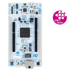
STM32 Nucleo-144 development board with STM32H743ZIT6 MCU, supports Arduino, ST Zio and morpho connectivity
Overview
The STM32 Nucleo-144 board provides an affordable and flexible way for users to try out new concepts and build prototypes with the STM32 microcontroller, choosing from the various combinations of performance, power consumption and features. The ST Zio connector, which is an extension of Arduino™ Uno, provides access to more peripherals and ST morpho headers make it easy to expand the functionality of the Nucleo open development platform with a wide choice of specialized shields. The STM32 Nucleo-144 board does not require any separate probe, as it integrates the ST-LINK/V2-1 debugger/programmer and it comes with the STM32 comprehensive software HAL library, together with various packaged software examples, as well as a direct access to the ARM®mbed™online resources.
Microcontroller key features
- Core
- 32-bit Arm® Cortex®-M7 core with double-precision FPU and L1 cache:
- 16 Kbytes of data and 16 Kbytes of instruction cache
- Frequency up to 400 MHz
- MPU
- 856 DMIPS/ 2.14 DMIPS/MHz (Dhrystone 2.1)
- DSP instructions
- 32-bit Arm® Cortex®-M7 core with double-precision FPU and L1 cache:
- Memories
- Up to 2 Mbytes of Flash memory with read-while-write support
- 1 Mbyte of RAM: 192 Kbytes of TCM RAM (inc. 64 Kbytes of ITCM RAM + 128 Kbytes of DTCM RAM for time critical routines), 864 Kbytes of user SRAM, and 4 Kbytes of SRAM in Backup domain
- Dual mode Quad-SPI memory interface running up to 133 MHz
- Flexible external memory controller with up to 32-bit data bus: SRAM, PSRAM, SDRAM/LPSDR SDRAM, NOR/NAND Flash memory clocked up to 133 MHz in Synchronous mode
- CRC calculation unit
- Security
- ROP, PC-ROP, active tamper
- General-purpose input/outputs
- Up to 168 I/O ports with interrupt capability
- Reset and power management
- 3 separate power domains which can be independently clock-gated or switched off:
- D1: high-performance capabilities
- D2: communication peripherals and timers
- D3: reset/clock control/power management
- 1.62 to 3.6 V application supply and I/Os
- POR, PDR, PVD and BOR
- Dedicated USB power embedding a 3.3 V internal regulator to supply the internal PHYs
- Embedded regulator (LDO) with configurable scalable output to supply the digital circuitry
- Voltage scaling in Run and Stop mode (5 configurable ranges)
- Backup regulator (0.9 V)
- Voltage reference for analog peripheral/VREF+
- Low-power modes: Sleep, Stop, Standby and VBAT supporting battery charging
- 3 separate power domains which can be independently clock-gated or switched off:
- Low-power consumption
- Total current consumption down to 4 μA
- Clock management
- Internal oscillators: 64 MHz HSI, 48 MHz HSI48, 4 MHz CSI, 32 kHz LSI
- External oscillators: 4-48 MHz HSE, 32.768 kHz LSE
- 3× PLLs (1 for the system clock, 2 for kernel clocks) with Fractional mode
- Interconnect matrix
- 4 DMA controllers to unload the CPU
- 1× high-speed master direct memory access controller (MDMA) with linked list support
- 2× dual-port DMAs with FIFO
- 1× basic DMA with request router capabilities
- Up to 35 communication peripherals
- 4× I2Cs FM+ interfaces (SMBus/PMBus)
- 4× USARTs/4x UARTs (ISO7816 interface, LIN, IrDA, up to 12.5 Mbit/s) and 1x LPUART
- 6× SPIs, 3 with muxed duplex I2S audio class accuracy via internal audio PLL or external clock, 1x I2S in LP domain (up to 133 MHz)
- 4x SAIs (serial audio interface)
- SPDIFRX interface
- SWPMI single-wire protocol master I/F
- MDIO Slave interface
- 2× SD/SDIO/MMC interfaces (up to 125 MHz)
- 2× CAN controllers: 2 with CAN FD, 1 with time-triggered CAN (TT-CAN)
- 2× USB OTG interfaces (1FS, 1HS/FS) crystal-less solution with LPM and BCD
- Ethernet MAC interface with DMA controller
- HDMI-CEC
- 8- to 14-bit camera interface (up to 80 MHz)
- 11 analog peripherals
- 3× ADCs with 16-bit max. resolution (up to 36 channels, 4.5 MSPS at 12 bits)
- 1× temperature sensor
- 2× 12-bit D/A converters (1 MHz)
- 2× ultra-low-power comparators
- 2× operational amplifiers (8 MHz bandwidth)
- 1× digital filters for sigma delta modulator (DFSDM) with 8 channels/4 filters
- Graphics
- LCD-TFT controller up to XGA resolution
- Chrom-ART graphical hardware Accelerator™ (DMA2D) to reduce CPU load
- Hardware JPEG Codec
- Up to 22 timers and watchdogs
- 1× high-resolution timer (2.5 ns max resolution)
- 2× 32-bit timers with up to 4 IC/OC/PWM or pulse counter and quadrature (incremental) encoder input (up to 200 MHz)
- 2× 16-bit advanced motor control timers (up to 200 MHz)
- 10× 16-bit general-purpose timers (up to 200 MHz)
- 5× 16-bit low-power timers (up to 200 MHz)
- 2× watchdogs (independent and window)
- 1× SysTick timer
- RTC with sub-second accuracy & HW calendar
- Debug mode
- SWD & JTAG interfaces
- 4-Kbyte Embedded Trace Buffer
- True random number generators (3 oscillators each)
- 96-bit unique ID
Nucleo board features
- Two types of extension resources
- Arduino Uno Revision 3 connectivity
- STMicroelectronics Morpho extension pin headers for full access to all STM32 I/Os
- On-board ST-LINK/V2-1 debugger/programmer with SWD connector
- Selection-mode switch to use the kit as a standalone ST-LINK/V2-1
- Flexible board power supply
- USB VBUS or external source (3.3 V, 5 V, 7 - 12 V)
- Power management access point
- Three User LEDs
- Two push buttons: USER and RESET
- USB re-enumeration capability: three different interfaces supported on USB
- Virtual Com port
- Mass storage (USB Disk drive) for drag'n'drop programming
- Debug port
- Ethernet 10/100Mbps
- USART
Board pinout
Pins Legend
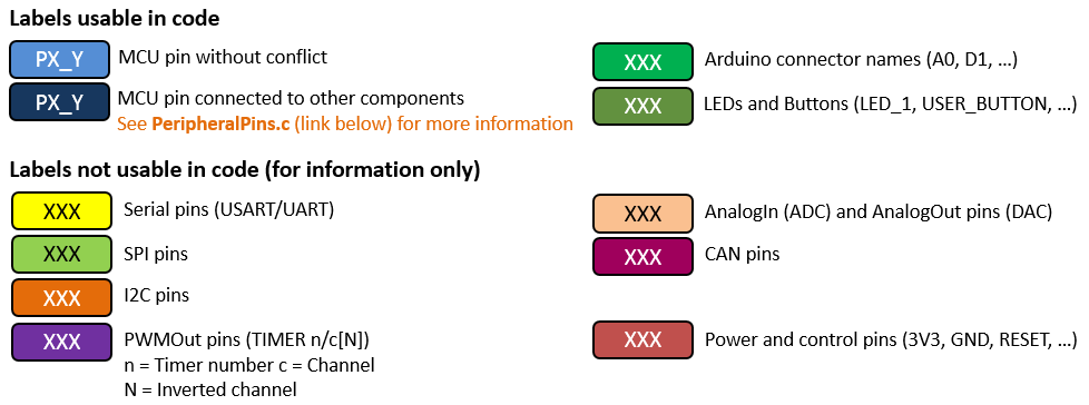
You can find more details on the available pins and labels in the PeripheralPins.c and PinNames.h files.
These files can be found in:
- ARMmbed/mbed-os repository on GitHub (up-to-date version, used with mbed CLI commands)
- mbed-dev library in developer.mbed.org (source files of the mbed library used on mbed compiler IDE)
TBD
Zio and Arduino-compatible headers
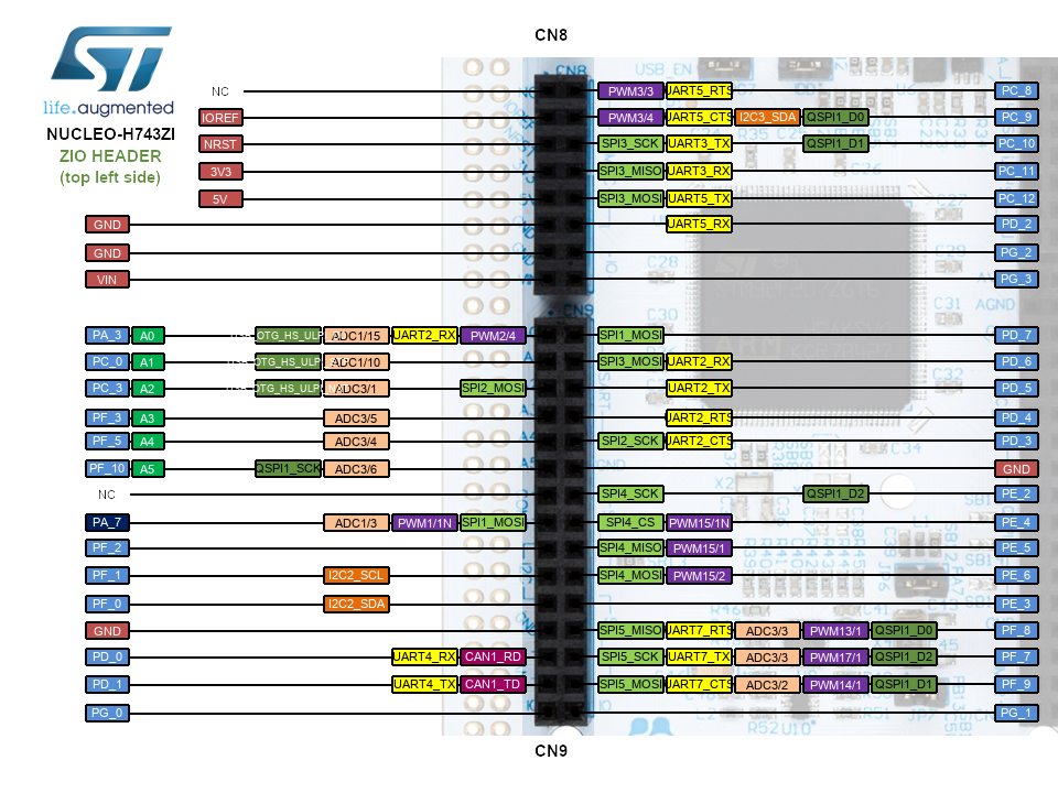
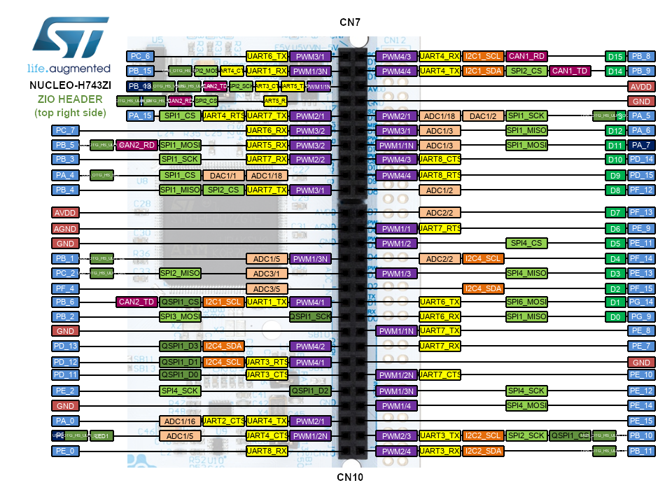
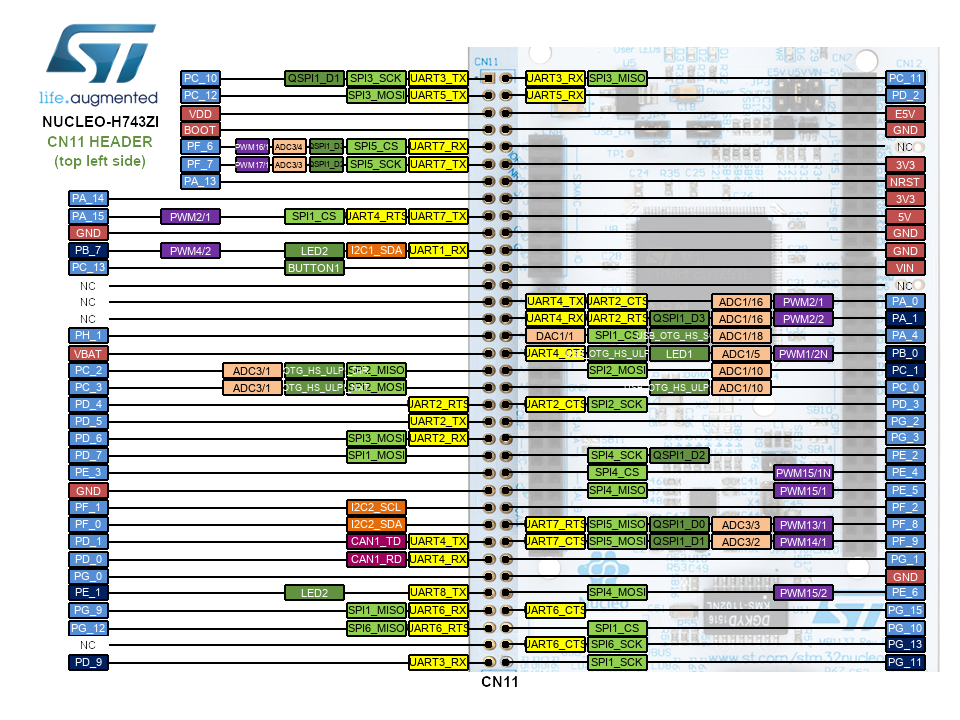
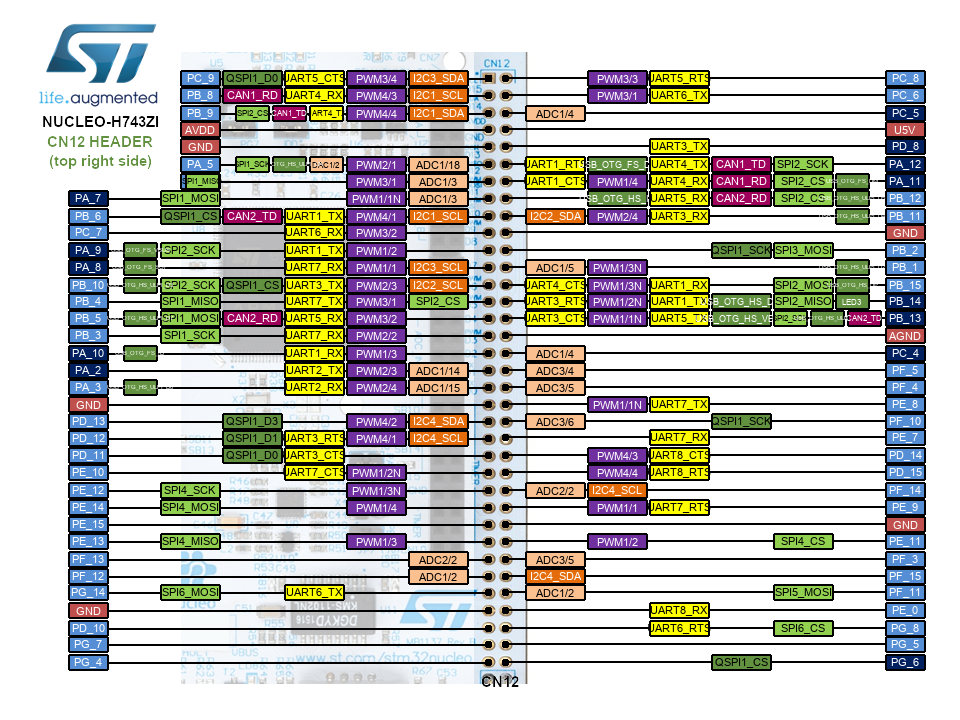
CN11 CN12 headers
Technical references
For more information, please refer to:
Known limitations
The following section describes known limitations of the platform. Note that general issues are tracked into the mbed repository available on GitHub.
- Conflict between Ethernet and SPI pins on Arduino D11
See HERE

