Problem with LED1 on LPC1768

22 Nov 2009 . Edited: 22 Nov 2009

I have LPC1768 only two days and I tested only LEDs because i don't hawe wires yet.

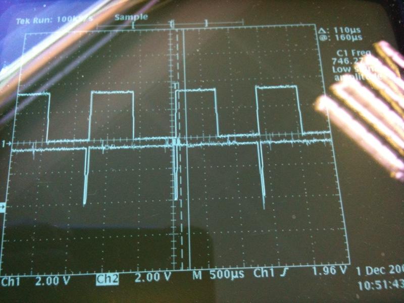
I have this problem: LED1 blink, but not by program.

My program is here:

#include "mbed.h"

PwmOut led1(LED1);
PwmOut led2(LED2);
PwmOut led3(LED3);
PwmOut led4(LED4);
 
#define PI 3.1415926
 
int main() 
{
    float f=0.0;

    while(1)
    {
        led1 = (sin((f      )*PI/180.0)+1.0)/2;
        led2 = (sin((f+ 90.0)*PI/180.0)+1.0)/8;
        led3 = (sin((f+180.0)*PI/180.0)+1.0)/32;
        led4 = (sin((f+270.0)*PI/180.0)+1.0)/128;
        wait(0.01);
        f+=1.0;
    }
}

Program is functional, but LED1 sometimes blink. I don't know why.

Please help me.


22 Nov 2009

Hey, just tried it on mine and the same issue occurs, might be a value too high or not enough power.

22 Nov 2009

If you change div to 2 for every LED like example bottom, then problem is still there.

The value returned to led1 and other is between 0 and 1 and it is normal.

        led1 = (sin((f      )*PI/180.0)+1.0)/2;
        led2 = (sin((f+ 90.0)*PI/180.0)+1.0)/2;
        led3 = (sin((f+180.0)*PI/180.0)+1.0)/2;
        led4 = (sin((f+270.0)*PI/180.0)+1.0)/2;
22 Nov 2009

Could be a scaling or casting issue the sin function returns a double not a float

22 Nov 2009

I am also getting the same effect. LED1 sometimes blinks when it is at its brightest, but the other LEDs don't do this.

I modified the code as below and it no longer happens.

        led1 = (sin((f      )*PI/180.0)+1.0)/2.1;
        led2 = (sin((f+ 90.0)*PI/180.0)+1.0)/2.1;
        led3 = (sin((f+180.0)*PI/180.0)+1.0)/2.1;
        led4 = (sin((f+270.0)*PI/180.0)+1.0)/2.1;

Curious.

22 Nov 2009

Hi Ales,

Thanks for this example. I was able to reproduce it and I think that is an interesting bug you've discovered there! I'm not quite clear whether it is hardware or software yet, but basically it is recreated by the following:

  • set the pwm output to 1.0
  • set the pwm output to just less than 1.0

It seems to be limited to that channel which makes me suspicious, as it is that channel which provides the global period counter in the hardware.

We'll see if we can track this down and fix or workaround it as appropriate. For now, to make your code work, you could just * 0.99 the value you assign to the led, as then it'll never reach 1.0, and hence never then move down from 1.0 (which is the point it fails). A hack, but will get your nice pulsating lights working beautifully!

Simon

22 Nov 2009

If I changed line to

        led1=1.0;

then there wasn't problem.

But, after change line to

        led1 = (((int)f)%2)==0 ? 1.0 : 0.99;

Problem is there.

22 Nov 2009

 I will use divide by 4, it is good.

Thank you, Simon.

22 Nov 2009

Try changing the code as follows; the effect is quite pleasing.

        led1 = (sin((f      )*PI/180.0)+1.0)/2.01;
        led4 = (sin((f+ 90.0)*PI/180.0)+1.0)/2.01;
        led3 = (sin((f+180.0)*PI/180.0)+1.0)/2.01;
        led2 = (sin((f+270.0)*PI/180.0)+1.0)/2.01;

01 Dec 2009

Hi,

Here is an update on the strange PWM behaviour on channel 1 (the one connected to LED1).

I wrote a simple test program that just accesses the hardware directly:


// Testing PWM channel 0 vs channel 1 behaviour, sford

#include "mbed.h"

PwmOut pwm1(p26);
PwmOut pwm2(p25);

int main() {

    uint32_t t = 10000;

    // set period
    LPC_PWM1->MR0 = t;
    LPC_PWM1->LER |= 1 << 0;

    while (1) {

        // set pulsewidth to 100%
        LPC_PWM1->MR1 = t;
        LPC_PWM1->MR2 = t;
        LPC_PWM1->LER |= 0x6;

        // wait for update
        while (LPC_PWM1->LER);

        // set pulsewidth less than 100%
        LPC_PWM1->MR1 = t - 500;
        LPC_PWM1->MR2 = t - 500;
        LPC_PWM1->LER |= 0x6;

        // wait for update
        while (LPC_PWM1->LER);
    }
}

As you can see, this just switches between 100% and less than 100% pulsewidth on two channels (1 and 2). Identical code for each channel. But here is the result:

Top is channel 1 (displaying the problem we see), bottom is channel 2 (what I'd expect). I'm suspicious that the problem is only on channel 1, which is "more connected" with channel 0, which is used for the period counter. Anyone see something I've overlooked here, or have an explaination?

Thanks,
Simon

01 Dec 2009 . Edited: 01 Dec 2009

You're still using the mbed library to initialise the port, could it be something in the port init?

If they're identical, check the assembler output from the compiler, the optimiser might be doing something quirky.

These are the points when you need JTAG

18 Dec 2009

Hi, has anybody representation of the case?

18 Dec 2009

Hi Ales,

This problem has been tracked down now to behaviour in the hardware (thanks especially to Sergio @ NXP!), and I've put in a work around the next version of the library which i'll put live soon. This will therefore fix this issue.

For reference: the match register MR1 (controlling the channel pulsewidth) should never be set equal to the value in MR0 (the global period).

Thanks,
Simon

19 Dec 2009

So is this actually a hardware 'problem' with the IC or just an implementation issue with the software?

19 Dec 2009 . Edited: 19 Dec 2009

Hi Andrew,

Andrew Harpin wrote:
So is this actually a hardware 'problem' with the IC or just an implementation issue with the software?

It is a behaviour of the hardware not discussed in the manual, so I guess it is an omission from the manual or a hardware errata (depending on what was intended/specified for the hardware). The workaround is pretty easy so no major problem.

Simon

16 Jan 2011

I think I discovered this same problem (and this note from a year+ ago). I was running a hardware test program across the PWM channels and the LEDs. After the first few steps, there appears to be an interaction between the PWM channels and the LEDs.

PWM_Verification

This seems to demonstrate it quite readily.

Simon, you mentioned implementing a work around in the "next" version of the library in the 18 Dec 2009 message. Would you have expected me to then not have this problem with a program just built moments ago?

Dave

16 Jan 2011

Hi David,

This is actually not the same behaviour, and the problem described in this thread was fixed in a library release.

The behaviour you are seeing is expected (but only if you know the reason!). There are 6 hardware PWM channels, and these can be routed out to the pins p21-p26. However, 4 of them can also be routed to the LEDs instead. So the behaviour you describe is when you route a channel out to both outputs, and hence see the result of changing one PWM channel in two places.

Thanks for taking the time to put together a program; made it very easy to understand the question and context. I'm sure others will find this very useful to understand what is going on.

I've also updated the handbook to explain this behaviour better, see:

Hope that makes everything more clear,

Simon