Little project involving mbed and 12v computer fans

26 Aug 2010 . Edited: 26 Aug 2010

Hello,

I have a bunch of electronic devices (internet DSL access, firewall, wifi router, GuruPlug, NAS...) in a cupboard in my office and as the weather is very warm, some devices are halting because of heating issues and I do not want to leave the door open...


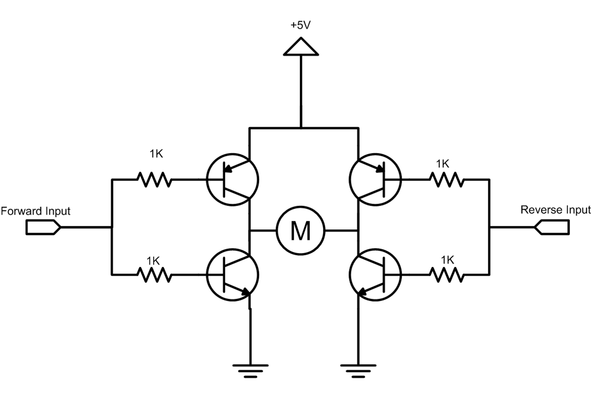
I want to install two 8cm fans in the cupboard to get rid of warm air. I know how to mesure temperature with a one wire thermo with the mbed and I want to start the fans when Temperature is too high. I want to use a pwmOut to drive the fans from 4V to 12V.

pwmOut is 0 to 3.3.V...


I just do not know what king of electronic equipment I should use between the 2 fans and the mbed...

Anyone could give me some advice on this very easy problem ;-) ?


Thanks in advance.

26 Aug 2010

Hi Stephane,

You could use a simple NPN transistor with the PWM output connected to the base? Or if you want something a bit more meaty a MOSFET?

26 Aug 2010

Hi Stephane.

Between the mbed and your two fans you may use 1 NMOSFET + 1 schottky diode. The NMOSFET must have a gate to source threshold voltage (Vgs_th) lower than 3.3 V (so that it can be turned on by the 3.3 V coming out of your mbed), a Vds_max higher than 12 V, and a Ids_max higher than approx 1 A. For instance, this one:

http://uk.farnell.com/fairchild-semiconductor/fds8884/mosfet-n-so-8/dp/1504995

and it is quite cheap.

The schottky diode must sustain 12 V of reverse voltage, and also 1 A of current. For instance, this one:

http://uk.farnell.com/nxp/pmeg3020ej-115/schottky-rect-30v-2a-sod323f/dp/1757772

Connect:

1) The two fans in parallel.

2) The ground of the mbed to the ground of your +12 V supply.

3) One node of the group of two fans to the drain (D) of the NMOSFET.

4) The other node of the group of two fans to your +12 V supply.

5) The source (S) of the NMOSFET to your ground.

6) The gate (G) of the NMOSFET to your pwmOut output from the mbed.

7) The schottky diode in anti-parallel with the group of the two fans, so that the cathode of the diode touches +12 V, and the anode touches the drain of the NMOSFET. It will act as a freewheeling diode, letting the current through the inductance inside the fans to extinguish through it, after you have turned off the NMOSFET.

That's it. Modulate the duty ratio of pwmOut as desired. The fans will produce an air flow (not linearly) proportional to that duty ratio.

Best.

26 Aug 2010

You could probably do that with a few Op Amps and/or logic gates.

Ex: use a comparator.  Set op amp rails to 4V and 12V, connect (-) op amp input to a voltage source between 0V and 3.3V, connect (+) op amp input to the pwm output pin on the mbed, and connect the op amp's output to the fan's pwm input.  When the mbed outputs 0, the op amp will output 4V, when the mbed outputs 3.3V, the op amp will output 12V.

27 Aug 2010

Op-amps used that way will dissapate too much heat.. General opamps usually limit the current to 10-40mA. That means, for the average 8cm fan (I have a 150mA one) you would need way to many opamps to get it to work properly. Also you would need to a low value resistor to each opamp output before connecting them together to balance the current evenly accross each opamp. Logic gates could work (if you already have some) but you would still need the diode and current output could still be an issue.

An easy solution would be:

http://www.sparkfun.com/commerce/product_info.php?products_id=9457

http://www.sparkfun.com/commerce/product_info.php?products_id=9479

I highly recommend you use a motor driver. If you use discrete parts, you have to worry about driving the gate/base properly (and not to damage the mbed pin).

Let us know how it goes!

27 Aug 2010

Thanks to everyone !

I think I why make a litle demo with the NPN transistor to validate my coding and go for a motor driver from Sparkfun for the real stuff, thus I will learn how to use it for another project involving a robot with wheels.

Cheers

29 Aug 2010 . Edited: 01 Sep 2010

You might want to just go ahead and just get a dual H-bridge motor driver module so that you could also reverse the two fans and two robot wheels. It has the entire power circuit already on an IC or PCB. I have also seen some cases where fans work better cooling blowing in than out. To also reverse a DC motor, you need four power transistors. Notice the H shape - that is where the name comes from. The circuit shows 5V DC power, but can be higher as needed for the DC motor. Don't try reverse and forward at the same time on this circuit unless you want smoke. The more complex circuits fix this and add an active brake state that shorts the pins on the motor. The protection diodes are not shown here, but are included in most of the H-bridge modules. Your PWM modulation rate needs to be in the Khz range. Too slow and the motor will buzz. Don't use analog out to control speed, it will take more power and just heat up the transistors.

http://www.pololu.com/catalog/category/11 has the smallest ones I have seen for high current - used in moving electric car seats - also some others at

Robot Electronics, Sparkfun, Acroname, Lynxmotion, Robotics Connection,

You need to know how much current the motor needs to select a transistor or H-bridge that can handle it. In some cases you might even want a heatsink on it!

In general the larger the motor, the larger the current and the more money you need for the H-bridge and motor power supply. A big cap is also a good idea on the power, since motors draw a lot of current when they first start.

Below are a couple of dual the H-Bridge modules I have used in robots.. Pololu uses an ST IC and the older one on the right uses discrete parts