Sending Break Character

04 Mar 2010

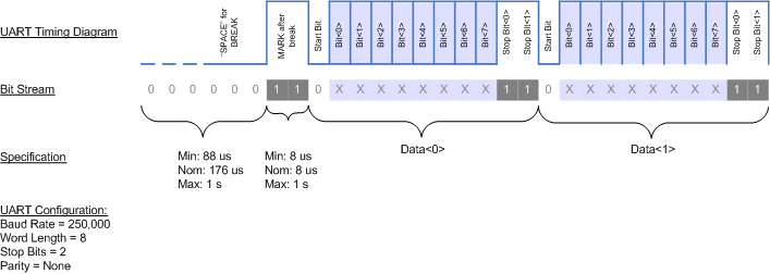
Does someone know how to send a break character over UART1? I have to reset a device that requires a break character to be sent to enter reset mode.

Asif

04 Mar 2010

Try if this works:

serial.putc(3);

This will send Control-Break (^C).

Otherwise please provide more details about the device and how you send break with other software.

04 Mar 2010

Unfortunately, sending Ctl-C will not work.  BREAK is a kind of out-of-band signal.  You need to set the BREAK bit (bit 6 of U1LCR) high, wait at least one character length -- 10 bits -- then reset the BREAK bit.  For good measure, I'd BREAK for two character spans, or 20 bits.

The 10 and 20 come from the number of bits in a character:  1 start bit, 8 data bits, 1 stop bit, assuming the usual setup.

At 9600 bps, one bit lasts 1/9600 seconds.  Twenty bits takes 20/9600 seconds, or a little over 2 milliseconds.

Hope this info helps.

Regards,

-Mike

05 Mar 2010

Thank you Mike. Got it working as following:


void SendBreakUART1(void)
{
LPC_UART1->LCR = 1;
wait(0.002);
LPC_UART1->LCR = 0;
}


Asif

08 Mar 2010

Sorry, the correct way is:

void SendBreakUART1(void)
{
    LPC_UART1->LCR |= 0x40;
    wait(0.0025);
    LPC_UART1->LCR &= ~(0x40);
}

22 Aug 2010 . Edited: 24 Aug 2010


Asif Iqbal wrote:

Sorry, the correct way is:


void SendBreakUART1(void)
{
    LPC_UART1->LCR |= 0x40;
    wait(0.0025);
    LPC_UART1->LCR &= ~(0x40);
}

I implemented this.  It successfully creates a break; however, I measured the TX line going HIGH for the break.  I need the TX line to go low for a break for a specific protocol to be met.  I need the break to be 180usec or so. Is this possible?  Where would I look for documentation?

Here's a timing diagram of what I am trying to accomplish.  I can accomplishe the "MARK after break", but I need to know how to create the "SPACE for break".

24 Aug 2010

Hi Philip,

If you send a break, the TX pin should go low (its steady state is high) as you require.

Here is an example I just wrote to show break in action.

// show break takes tx low, connect p9-p11
#include "mbed.h"

DigitalOut myled(LED1);
Serial s(p9, p10);
DigitalIn x(p11);

int main() {
    myled = x;
    wait(1);
    
    LPC_UART3->LCR |= 0x40;
    while(1) {
        myled = x;
    }
}
The led will go off after 1 second.

Maybe you are measuring something else? Or are you using a TTL-RS232 converter and looking at the signal after that (where it would be inverted)? Or perhaps you are sending break to the wrong UART, and thinking the next transmission includes the break when it doesn't.

I think the hardware should be doing what you desire, so would be interesting to get to the bottom of this!

Simon

25 Aug 2010 . Edited: 25 Aug 2010

Simon,

Thank you for your quick response.  It was very helpful.

My problem was that I assumed UART1 to be p9 and p10 since they are the lowest order pins.  The breaks are working beautifully now.  Is there any documentation on this?  I feel like I'm working in the dark.

I have a new issue: I am not able to create a data stream like the diagram I specified above using the Serial putc or printf commands.  The data seems to be there, but not how I would expect.  Both the putc and printf commands seem to be outputing the 4 least significant bits at a time instead of 8 bits at a time:

  • start bit ("0"b)
  • 4 data bits ("1000"b, using my code below)
  • 2 stop bits ("11"b)

Also, I put the putc in a for loop for 3 iterations.  2 of the iterations got lost or cut off because only one data message shows up.  Is there something I'm missing?

-Philip

Here's my code:


#include "mbed.h"

Serial dmx(p9,p10);

int main() {
    dmx.baud(250000);
    dmx.format(8,Serial::None,2);

    while (1) {

//  Tried implementing a for loop to send a series of bytes on TX
            for (int n=0; n<3; n++) {  
                while (!dmx.writeable()) {}   // played with adding a while loop to idle untile dmx was writable; doesn't solve the problem.
                dmx.putc(0x51);               // 2 of the iterations don't show up or get cut off. The most significant nibble (0x5_) doesn't show up.
            }

            // BREAK
            LPC_UART3->LCR |= 0x40;
            wait_us(180);
         
            // MARK AFTER BREAK         
            LPC_UART3->LCR &= !(0x40);
            wait_us(100);
   
        running_led = !running_led;
    }
}
26 Aug 2010 . Edited: 26 Aug 2010

Hi Philip,

Whilst this baffled me for a bit how you could be seeing this behaviour, looking at your code it is all derived from a little bug-et. What you intended was spot on, but what you wrote is actually subtly different. The hiccup is ! means logical, and ~ means bitwise. So for example:

LPC_UART3->LCR &= !(0x40); // this means AND with 0x00
LPC_UART3->LCR &= ~(0x40); // this means AND with 0xBF

So that means in your code, you are clearing the entire LCR register, which includes fields for e.g. the character length.

Try swapping ! for ~, and things should spring in to life (or at least be closer!).

(It is avoiding having to worry about low-level bugs like this that is a real driver for mbed, so we'll aim to fold break in to the libraries so no-one has to trip up again!).

Thanks,
Simon

29 Aug 2010 . Edited: 29 Aug 2010

Hi Simon,

Thank you so much for the help on this!  That solved my problem with the data length.  So subtle these syntax errors! I'm a LabVIEW guy trying to hack at text based code.

I had to solve one last problem that was really boggling me to get the protocol finally working.  I had to insert a minimum 76us delay at the end of the loop before looping back around and executing the break again.  I determined the value 76us empirically; 75us will not work.  Looking at the TX line on a scope, I noticed without the 76us delay, there is an extra start bit and one data bit after the expected stream of data.  The 76us is a constant value necessary regardless of the size of the data (SLOTS, number of for loop iterations in my case).  Here's my code:

            // BREAK
            LPC_UART3->LCR |= 0x40;
            wait_us(time_BREAK);
         
            // MARK AFTER BREAK         
            LPC_UART3->LCR &= ~(0x40);
            wait_us(time_MAB);

            //TRIGGER
            trigger = 1;
            wait_us(40);
            trigger = 0;
            
                dmx.putc(0x00);               // DMX[0] must be 0x00 or 0xFF

            for (int n=0; n < SLOTS; n++) {     // repeat writing the DMX UART for the number of slots
                while (!dmx.writeable()) {}   
                dmx.putc(0x55);               
            }

            // WAIT BEFORE LOOPING BACK TO BREAK
            wait_us(76);

I'd be interested to hear from you if you have any idea about the reason for this behavior.  Without knowing the system design, my conjecture is that perhaps the microprocessor takes around 76us to execute the UART data transfer and that the data is being transmitted from some buffer independently of the microprocessor.  This is very curious...

Thanks again!  Now that I have this UART communication working, it should be downhill (hopefully).

-Philip