Mbed and Gsm modem.

21 Jan 2010

Hey all,

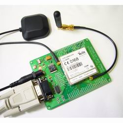
so i just ordered a GSM module and eval board from Spark Fun. http://www.sparkfun.com/commerce/product_info.php?products_id=9427

Just wondering if anyone has played around with Mbed's and GSM/GPRS Modules?

21 Jan 2010

Hi Glen!

I have tried to make my old cellphone (Ericsson T29s) work with LPC1768.
I ran into some issues, but I wouldn't expect those issues with a GSM Modem.

Does the eval board support SMS in text mode? If it does, you won't have to convert the SMS from PDU format to Text, if that's what you need.

What is your project for?

/ Lerche

21 Jan 2010

Hello Christian,

Thanks for the quick reply. Yep, sms is supported in text mode. So that's definatly a bonus. I was looking into the Rocket Project, and they used gprs (i assume a GSM Module) so i have high hopes. I'm making a remote monitering module for my parents, my dad lives in canada out by a lake and is usually away from home quite a bit. Being paranoid, he's always scared something will freeze or a gas leak or a flood. Something to give him piece of mind :)


21 Jan 2010

Wow, that sounds like a nice project!
PLease be sure to update when you got something to show the world! :-)

/ Lerche

30 Aug 2010 . Edited: 30 Aug 2010

Students here have used the GSM modems from Sparkfun and Enfora (image below) to place calls and send and receive SMS in over a dozen projects with other microcontrollers. With a serial interface you can send and receive SMS messages using some simple AT commands. A USB modem interface would be faster for data service but quite a bit more mbed code work! Make sure you have the right serial port baud rate for the modem and check if you need a null modem serial cable. You have to plug in a SIM module. You can probably use the one from your cell phone. A few carriers seem to lock to the serial number of your regular phone and turn off your service when it changes (with the modem), but it comes back as soon as you put the SIM back in your old cell phone. Most carriers work just fine and don't check. Don't forget the antenna and wall wart, sometimes they are sold separately. I would try the AT sequence out first using a serial cable on your PC and a terminal emulation program like hyperterm or realterm before writing mbed code to do it. On the Enfora GSM modem it is just as simple as this:

After the modem is properly configured, to send an SMS message the following command is sent from the computer at 115K Baud on the serial port:


AT+CMGS=”18005551212”


The modem responds with

              >

And next the message text is then sent by the computer with:


SMS Message text is here ^Z


And finally the modem responds after a slight delay to acknowledge sending the SMS message with:

+CMGS: number

OK

A similar command syntax that varies somewhat between the different cell phone service providers can also be used to send the SMS message text to an email account. Received SMS messages can also be read back to the computer over the serial link. Most modems have a manual that lists the AT commands on the company web page and be sure to get it! A few even have ap notes on sending SMS messages. It is a bit harder to find any place that sells the enfora modems, but the small case is easier to deal with.


Sparkfun modem                                                                      Enfora modem

02 Dec 2010

Hello,

does any of you know of a project that uses USB to access a mobile phone?

That would be very interesting.

Henry

09 Feb 2011

/media/uploads/4180_1/p_rs232.jpg

I think some of the serial modems require handshake lines. There is an RS232 breakout board from Pololu that supports all of handshake lines. I plan on trying it soon.

07 Mar 2011

This student project got it working using the Pololu breakout board and they had to jumper some handshake lines

http://mbed.org/users/bhoomi1810/notebook/sending-gps-co-ordinates-as-text-message/

http://mbed.org/media/uploads/bhoomi1810/_scaled_dscn0928.jpg

14 Jun 2011

Hi Jim & all,

I am having a challenge interfacing my MBED with a GSM modem (maestro 20). I was able to get the modem working well with Hyperterminal and it responded to all the AT commands i sent to it. My aim is to operate this modem using the MBED and so far i have been able to create a virtual serial port for the MBED (by installing the serial PC driver) and i was able to communicate with it via TeraTerm and also ran some tutorial codes on it and it worked. My challenge now is how to connect my GSM modem so that it will take command from the MBED. The modem has physical RS 232 serial connection and i find it difficult connecting both the modem and MBED at the same time to the serial port, in that once the MBED is connected via the virtual port it will not recognize the physical connection of the modem. Also i am very new to coding and i will love it if i can get some MBED code for sending AT commands. My project involves identifying and displaying the signals/protocols transmitted between a GSM modem and a BTS when the modem does the following: (1) voice call (2)sends SMS (3) Powered up and initialize

I will greatly appreciate you guys coming to my help as have been stuck for days trying to explode my head.

Thanks a lot.

15 Jun 2011

Hi, I used NetservicesMod lib code (http://mbed.org/users/andrewbonney/libraries/NetServicesMod/lpcb7f) as a starting point and connect a Wavecom modem through to a UART port. Initially, I couldn't make the PPP connection connect properly. Then I found that after I put a 10ms delay in PPPNetIf::poll() in PPPNetIf.cpp. It connects OK. Does anyone know why we need to put a delay?

here is the PPPNetIf::poll() I modified:

void PPPNetIf::poll() {

if(!m_connected) return; LwipNetIf::poll(); static u8_t buf[128];

// I put a delay here wait_ms(10); wait 10 ms ////

int len; do { len = sio_tryread((sio_fd_t) m_pIf, m_buf, BUF_SIZE); if(len > 0) pppos_input(m_fd, m_buf, len); } while(len>0); }

04 Jul 2011

Anthony, when you connected the modem to your PC, how was it connected? You mention in your post that it is a RS-232 device. Do you need to use a RS-232 to USB converter or does your PC have an old school serial connection? If the device is actually using RS-232 then you will need to use a level shifter such as a MAX232 or MAX233 to convert from RS-232 levels used by the modem to TTL levels used by the mbed chip. Connecting the modem up directly to the serial pins on the mbed could damage the mbed as it can't handle the larger positive/negative voltages used by RS-232.

05 Jul 2011

Adam Green wrote:

Anthony, when you connected the modem to your PC, how was it connected? You mention in your post that it is a RS-232 device. Do you need to use a RS-232 to USB converter or does your PC have an old school serial connection? If the device is actually using RS-232 then you will need to use a level shifter such as a MAX232 or MAX233 to convert from RS-232 levels used by the modem to TTL levels used by the mbed chip. Connecting the modem up directly to the serial pins on the mbed could damage the mbed as it can't handle the larger positive/negative voltages used by RS-232.

Adam,Thanks for your response. When i connected the modem rto the PC i made use of the serial com port (old school) at the back. It was wheni noticed that the port reflects as com1 and the serial USB reflects as com3 that i decided to connect the modem directly to the MBED using its RS-232 cable. This was done by soldering some pins of a DB9 connector shell (male) and connecting it to the MBED (as mentioned in my message to you), i then connected the connector shell to the female end of the GSM modem RS-232 cable and finally connecting the MBED to the PC via the USB. Find below the pictures of the modem and the MBED.

/media/uploads/muyenchy/_scaled_dsc00576.jpg /media/uploads/muyenchy/_scaled_dsc00577.jpg /media/uploads/muyenchy/_scaled_dsc00573.jpg

Am looking into your suggestion of MAX232 level shifter. Will appreciate your further response.

Regards

05 Jul 2011

I don't have any experience with interfacing to a GSM modem so I don't know how much help I will be.

Do you have a schematic for the base board that you are using to interface with the mbed chip? Which pins of the DB-9 connector did you connect to which pins of this board? You will definitely want to use a level shifter for this device. Jim Hamblen links to an article above describing how students got such a project working at this link and they used a level shifter breakout board from Pololu. They also placed a jumper between the CTS and DSR pins.

05 Jul 2011

Adam Green wrote:

I don't have any experience with interfacing to a GSM modem so I don't know how much help I will be.

Do you have a schematic for the base board that you are using to interface with the mbed chip? Which pins of the DB-9 connector did you connect to which pins of this board? You will definitely want to use a level shifter for this device. Jim Hamblen links to an article above describing how students got such a project working at this link and they used a level shifter breakout board from Pololu. They also placed a jumper between the CTS and DSR pins.

Adam, it was actually the project at the link you gave that am using as a guideline. I am not using any board for the interfacing of the MBED. My connection is shown in pictures i uploaded. I actually connected pins 2, 3, 5, 6 and 8 of the DB-9 connector to pins RX, TX, GND, GND and GND of the MBED respectively (as suggested by the students). There after i connected the MBED to the PC via its USB cable. I have ordered for the level shifter you suggested. hopefully the solution is nearer. Thanks for the great help you have been. Responding to my inquiry is enough help to me. Thanks and i will fill you in on developments but any further hints is very welcomed.

05 Jul 2011

Anthony Osho wrote:

I am not using any board for the interfacing of the MBED.

I was referring to the green PCB to which you have the MBED installed in your photos. What is that board? Do you have schematics for it?

05 Jul 2011

Adam Green wrote:

I was referring to the green PCB to which you have the MBED installed in your photos. What is that board? Do you have schematics for it?

Ohh, the green PCB. I dont have the schematics. The MBED actually came like that with it already fixed unto the board. Its called the MBED WattBob I ARM development system kit (comes in a carry box). I will try to get my hands on the schematics.

26 Aug 2011

Hi Adam and everyone, sorry I have been away for a wee while due to surgery.Glad to be back and thank for the assistance so far.I will like to say that I finally got my setup working, I had a logic shifter constructed using MAX232 and interfaced it between the MBED development system and the GSM modem. Now I can get the MBED to communicate with the modem and the results displayed on the screen. I have a challenge right now, for anybody that is familiar with GSM process/protocols, is there a way to monitor using my above set-up, the signalling processes that occurs during GSM voice call initiation? I really would appreciate if someone could come to my rescue and let me know if its possible to monitor protocols like RACH, AGCH, SDCCH, TCH etc. using the MBED and the GSM modem.

Hoping to hear from anyone soon. Thanks

26 Aug 2011

Adam Green wrote:

I was referring to the green PCB to which you have the MBED installed in your photos. What is that board? Do you have schematics for it?

Hi Adam and everyone, sorry I have been away for a wee while due to surgery.Glad to be back and thank for the assistance so far.I will like to say that I finally got my setup working, I had a logic shifter constructed using MAX232 and interfaced it between the MBED development system and the GSM modem. Now I can get the MBED to communicate with the modem and the results displayed on the screen. I have a challenge right now, for anybody that is familiar with GSM process/protocols, is there a way to monitor using my above set-up, the signalling processes that occurs during GSM voice call initiation? I really would appreciate if someone could come to my rescue and let me know if its possible to monitor protocols like RACH, AGCH, SDCCH, TCH etc. using the MBED and the GSM modem.

Hoping to hear from anyone soon. Thanks

24 Sep 2011

Hi Anthony Osho. I have the same WattBoB kit. I just can't seem to access the push buttons and leds, which is in the wattbob kit. Do you know the syntaxes or an example program for the same ?

Thnaks, Denny

-deleted-
11 Feb 2012
20 Nov 2014

Hi! can some one give me a code to read responses from GSM SIM 900 and display it on LCD? Thank you

31 Aug 2016

Hello could i please have code that is mbed compliant with the STM32F446 board to turn on and off multiple outputs using the gsm sim808 with the adafruit library thank you.

27 Mar 2017

Lukhanyo Pulumo wrote:

Hello could i please have code that is mbed compliant with the STM32F446 board to turn on and off multiple outputs using the gsm sim808 with the adafruit library thank you.

I'm working on something that addresses this. Right now the AT level is coming along well, and it is 100% callable from mbed OS. After that settles down, I plan to plug it into their network stack.

repo is here: https://github.com/malachi-iot/atcommander

Caveat: I don't plan compatibility with the Adafruit lib

04 Apr 2017

Hey @Malachi, we've already produced an AT command parser - https://github.com/ARMmbed/ATParser.

This AT command parser is in use for ESP8266 WiFi Interface - https://github.com/ARMmbed/esp8266-driver as well as the MulitTech dragonfly cellular interface - https://github.com/ARMmbed/mtsas-driver.

You guys can use the MultiTech driver for an example of creating an mbed-os cellular interface API.