Hi all, Hello Mario,
I am also having difficulties with the AnalogIn. As a simplest test I could think of, I connected the D/A output, pin 18, to an A/D input. Inputs AD0.2 and AD0.4 are really close by (pin 17 and 19) and can be conveniently connected using a jumper, like this:
 (Here it is pin 18 & pin19.)
The jumper can be pushed all the way down onto the pins. This makes for a very short connection, minimizing capacitive or inductive coupling to other sources besides the analog output. It also avoids connecting to digital ground or supply voltages.
It is then a simple matter to scan through all the 1024 D/A values and for each one of these acquire a set of A/D readings, for instance with a program like this:
dacadctodiskshort
The resulting binary file can be analyzed in various ways, for instance, using matlab:
fh=fopen('d:\out.txt','r');
d=fread(fh,[200,1024],'uint16');
fclose(fh);
d=floor(d/16)';
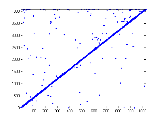
plot(d,'b.'); axis tight
The last line plots all the data points. For pin 17 on my mbed, the result looks as follows:

Most of the values are on the line y=4x, as one would expect for a 10 bit D/A and a 12 bit A/D, but unfortunately, there are quite a few points that do not seem to have been converted well by the A/D. And the bad news is that these are not just all 0x000 or 0xFFF, so it is hard to reject them programmatically.
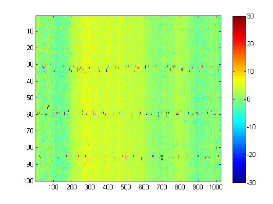
Interestingly, the 'misconversions' do not seem to come completely randomly, as can be shown using the following:
m=0:1023;
m=repmat(m'*4,1,size(d,2));
imagesc(d'-m',[-30 30])
colorbar
This shows the difference between the measured and expected A/D value as colors:

Clearly the misconversions come at more or less regular intervals.
I would be very interested to hear if other people get similar results...
Best regards,
Mischa
Hi all,
One of the main reasons I started with the Mbed is the availlability of the on-board AD converter. I already posted another topic about this. My experiences show that the analog part of the mbed design is not one of the best.
Today I started to experiment a little bit with it.
First I made a low pass filter with a buffer, so I wouldn't influence the output signal with the input impedance of the Mbed. Simple design, nothing fancy. Power source external +5V.
On the input is a pressure sensor MPXS 4100 connected. Yes I know, there are digital sensors with A/D conversion in it. But I want to connect more analog signals.
Resistors are 15k, capacitors are 10 nF, cutoff frequency is 1 kHz.
I checked the output signal of the second OpAmp with an oscilloscope, 2 mV/div, looks normal:
After that I connected the output of the second opamp to pin 20 of the Mbed and started to sample the signal. Variance > 10% in the measurements.
I connected the scope again on the output signal of the second OpAmpl with this result, still 2 mV/div:
After disconnecting pin 20 of the mbed the signal is again like the first image from the scope. So I connected the scope to pin 20 without anything else (open pin). Result (5 mV/div):
Since it is an open pin, this can happen. So I pulled it down to ground with a 1k resistor. Same signal as in the second scope image.
The resolution of the AD converter is 3.3 / 2^12, so appr. 0.8 mV. The signal I measured is 8 mV, or appr. 10% of the resolution, which is consistent with my measurements.
So mbed guys, is there a design error in the analog part of the board?