mbed Programmer
Mission Statement
To produce a low-cost programming platform that vastly simplifies the programming process for prototype-to-hardware migration.
Vision
I want this to be similar to a flash drive that when plugged into a PC will show up as a mass storage device. The device is then connected to the target PCB to be programmed. The User then uses the drag-and-drop process familiar to all mbed users to load the desired binary file onto the device. The target PCB is programmed by pressing a button on the device. The device provides feedback to the User via status and comms LEDs.
The whole process must feel like the mbed environment and programming process. It must be simple and give clear feedback to show that the target has been programmed.
Realisation
I started working on this project a few months ago after I heard about a team of engineers that wanted to use the mbed environment to develop a custom PCB. After completing the design they decided the best way to program it was to get an mbed, desolder the LPC1768 IC from it and connect flying leads to the SWD pins and connect them to the matching pins on the target PCB via a header. They then just dragged the binary onto the mbed and pressed the reset button. The mbed 'magic' chip then simply programmed the target device instead of the absent LPC1768!
While I thought this was an ingenious idea it also made me chuckle because it seemed a bit overkill. So I started to think about alternate way of doing it. I had already had experience of ISP programming (see my notebook page), and a cookbook page exists clearly explaining this method.
The problems with this method are that you need to convert the binary to hex and it takes a while to set-up. But the nail in the coffin is Flash Magic. Flash Magic is a great tool but legally you are only allowed to use it for personal use or prototyping (read the free license limitations here. If you wish to use it to make saleable product you need a licensed copy which costs around £400 + VAT (see here).
In a similar situation JTAG can be used to program the PCBs. This again can be very expensive with some JTAG programmers costing £1000s. In contrast I thought my device could be produced and sold for <£50
The mbed HDK should address this problem, But it is not ready yet. Also it will add cost to each and every PCB it is used on. My method is a one-off cost with very little added to the cost of the target PCB (just a programming header)
What am I gonna do about it?
So I started doing a lot of reading on the LPC1768 datasheet and searching on the web. I used the mbed community a lot and found that people had done most of the little bits I needed - just nobody had brought them all together.
The first thing I done was to get some flash memory where people can drag and drop their programs to. I then needed to get this appearing as a USB mass storage device (MSD) when it was connected to a PC (a big thanks to Little Llumpu for your work in this area). I then read a LOT of stuff about the FAT file system and wrote some code that looks through the files system and returns a pointer to the latest file written on the device that has a .bin file extension.
Following this was a LOT more reading on how to program the LPC1768 and the strange world of Uuencoding as well as the mechanics of how to write to the flash memory of the LPC1768 target device.
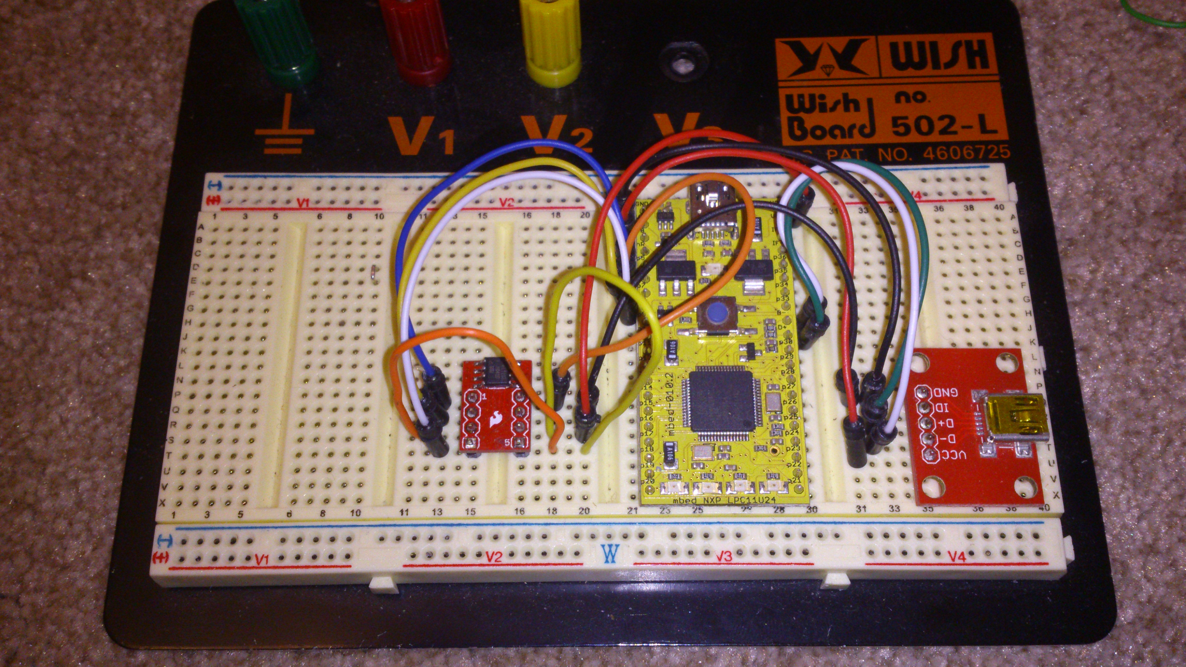
Finally I wrote some more code (for a hardware engineer I sure do write a lot of code!) that puts the target into, and brings it out of reset when it is programmed. Along the way I did my usual method of code development which involves lots of small chunks of code and lots of testing as I go. Finally I was left with a breadboard using an M0 mbed, a USB connector and a AT45 flash memory chip which together formed a system that would replicate the mbed 'magic chip' drag and drop programming environment.

Prototype to Hardware
Ironically I now needed to move from prototype to hardware and design and then program my custom PCB. The hardware design was pretty straight forward (that's my day job!) and I managed to get a small PCB made. The main thing I settled on at this stage was the pinout for the programming connector. I designed this in such a way that if one were to plug it in the wrong way round no damage would be done to either PCB.
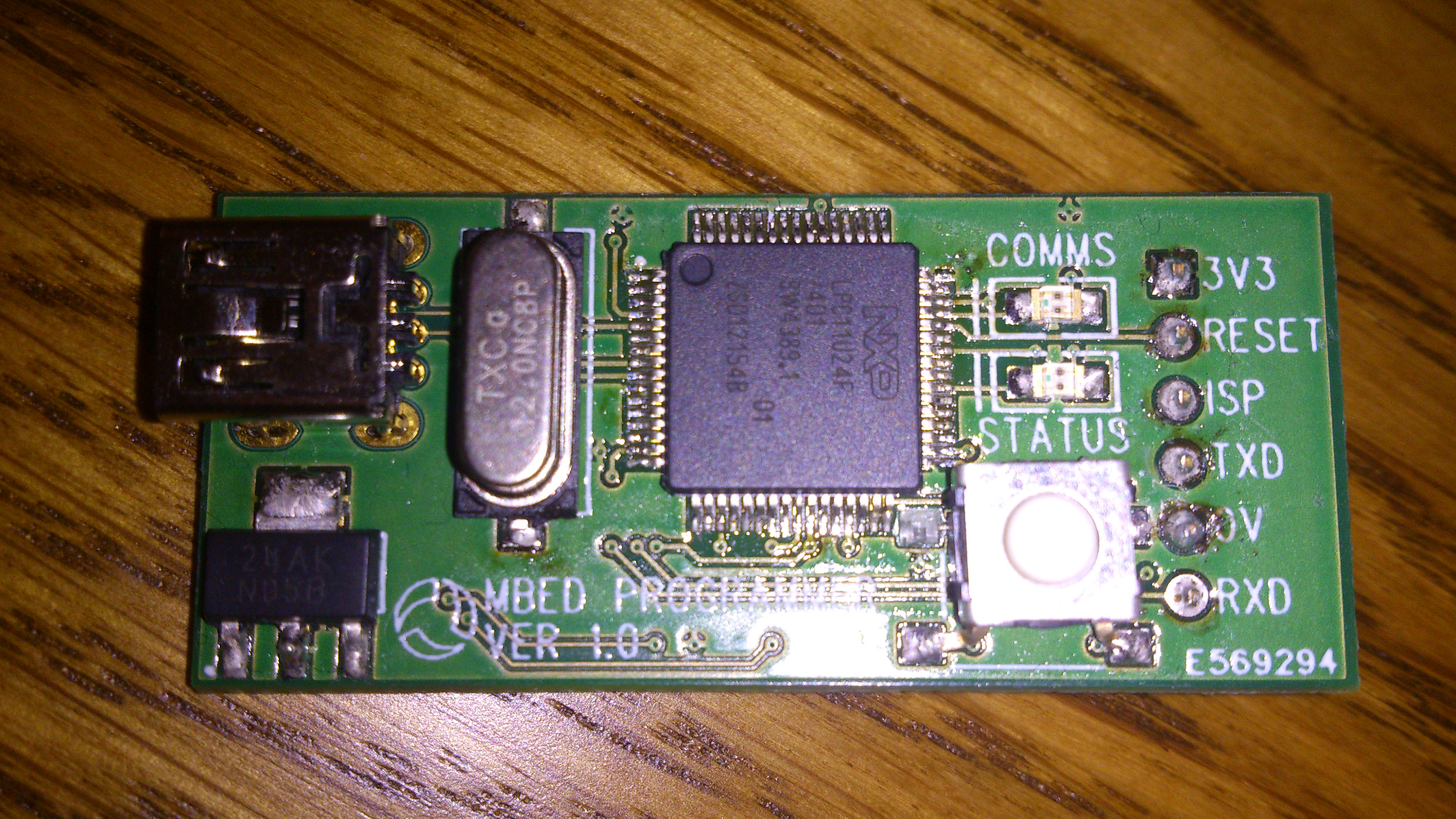
A photo of the PCB is presented below...

The PCB is pretty small and uses the same USB cable as the mbed. When plugged into a PC the device shows up as a flash drive where the same binary files the mbed complier produces can be drag and dropped. The target PCB is plugged into connector on the device and programmed by pressing the white button. Simple.
I made a youtube video talking you through the prototype. I plan to change the form-factor into something a bit more robust and then we'll see where we can go with this.
Comments welcome Martin
12 comments on mbed Programmer:
Please log in to post comments.


Hello Martin,
well done! Are you going to share details (schematic, code) of your programmer? What's the final hardware cost?