Pelion Device Ready Reference Designs – Production ready hardware
This blog shares some of the insights we have learnt from OEMs who are already shipping products in volume, and how our Mbed Enabled certification scheme, including Pelion Device-Ready Reference Designs will make the journey for manufacturers smoother in the future.

Embedded World is this week and we are seeing multiple projects culminating during the show, which will help OEMs reduce their time to production. IoT product volumes are growing, with an estimated Trillion deployments projected by 2035, proving the underlaying core technology is mature, but feedback has shown the journey to production could be smoother.
The Mbed team have been doing a lot of work behind the scenes to reduce the risk and effort required to build end user products. This blog shares some of the insights we have learnt from OEMs who are already shipping products in volume, and how our Mbed enabled Pelion Device-Ready Reference Designs will make the journey for manufacturers smoother in the future. We have also introduced (below) the first wave of physical boards derived from these proven Reference Designs which will work with Mbed OS and Pelion Device Management out the box.
What is a Mbed Enabled, Pelion Device Ready Reference Design?
In a nutshell, a reference design is a distilled blueprint describing how the absolute minimum hardware components (MCU+Radio+Memory+Security) should be connected to each other in order to run Mbed OS and benefit from all the features available from Pelion Device Management. It only specifies the logical connections of the components (i.e. a schematic), not where the components should be placed in a product which leaves you free to concentrate on the product’s unique features safe in the knowledge the IoT parts have already been proven for you.
Background- the Research Phase
While interviewing OEMs who used Mbed OS in their end products for the Built With Mbed page, we discovered a few recurring themes which prompted us to look at ways of improving the development experience.
For several years, developers have been experimenting with different hardware and cloud platforms before settling upon a preferred solution. With many developers liking access to starter kits, free access to cloud accounts for development purposes, and the desire for a single board consisting of proven hardware tested with an OS and cloud platform. “We need a way of avoiding experimentally matching an MCU with a radio shield, adding a secure element and inserting an SD card, this is all before we even start looking at which sensors to use”. The developer community felt this isn’t representative of end products, and introduces too many variables for a smooth concept to production experience.
We've also heard of the difficulties faced when testing a proof of concept in the field, with the frequent need to deploy the product in realistic environments using large development boards, (typically stacks of shields are Gaffer taped to the outside of the product under test).
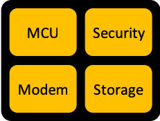
Wouldn’t it be nice to have compact boards that could be housed inside the PoC yet still flexible enough for development? Well, this is what we've set out to achieve with our Pelion Device Ready Reference Designs. The four fundamental blocks of a Reference Design include:

Reference Designs:
The Arm validation lab racks contain many standard development boards, plus a wide range of MCU+radio combinations designed by our hardware team. During testing, we ensure various combinations of MCU + radio + secure element + storage all function with the latest release of Mbed OS have been certified Mbed Enabled, including Pelion Device Management. The hardware we use in the lab is typically bulky and optimized for use in rack-mounted fixtures, as a result of all this testing we are certain the circuits work with the latest builds of Mbed OS which brings us to what’s included in a Pelion Device Ready reference design.

(Internally developed module + MCU boards used in the Arm validation labs.)
Mbed Enabled, Pelion Device Ready Reference Designs include:
- Schematics depicting how the four core components should be connected.
- Example implementation as used in our validation hardware (including Gerber files), we don’t expect anyone to recreate our test lab, its just for reference.
- Documentation.
- BOM.
- Checkpoint of the latest proven software.
- Reference Pelion Application is a version-controlled application which incorporates released versions of Mbed OS and Pelion Client. It includes all required drivers and has been proven to work with Pelion device management.
It doesn’t include:
- Sensors.
- Gerber files or physical layout because we have no idea what you are going to build.
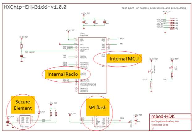
Just as long as the four fundamental components are connected as specified in the schematic then it will be connectable to Pelion Device Management. The Open Source Reference Designs are freely available from Github, at the time of writing there are four Wi-Fi and one NB-IoT designs available with many more arriving shortly. If there is a specific design you think we are missing please get in touch.

(Example schematic of a Wi-Fi reference Design depicting the four fundamental elements)
Boards designed specifically for Mbed and Pelion:
As stated above, a Reference Design is a set of design files, some of our distributors and board manufacturing partners have used those files and created hardware which runs the same as we see in our labs but in a form-factor suitable to a specific vertical market. When it comes to adding sensors there is a range of ecosystems to choose from: grove connectors, Arduino shield, MikroElektronika, xBee and many more, their Reference Design based boards have been created to take advantage of the most relevant and essential connector ecosystems. If you develop a proof of concept based on these boards and decide it is time to spin your custom board to meet your form-factor needs, just refer back to the core reference design files, copy them and layout a board as required knowing the software will continue to work because it’s all built on the same blueprints.
Here are a few examples of the first wave of boards being launched during Embedded World 2019:

Head to Github to see our constantly updated reference designs which will be complemented by new boards in the coming months.
You need to log in to post a discussion
