How to use the LPCXpresso54608's Touch Panel
This tutorial will show you how to utilize NXP's LPCXpresso54608 demo touch panel applications for use with Mbed OS.

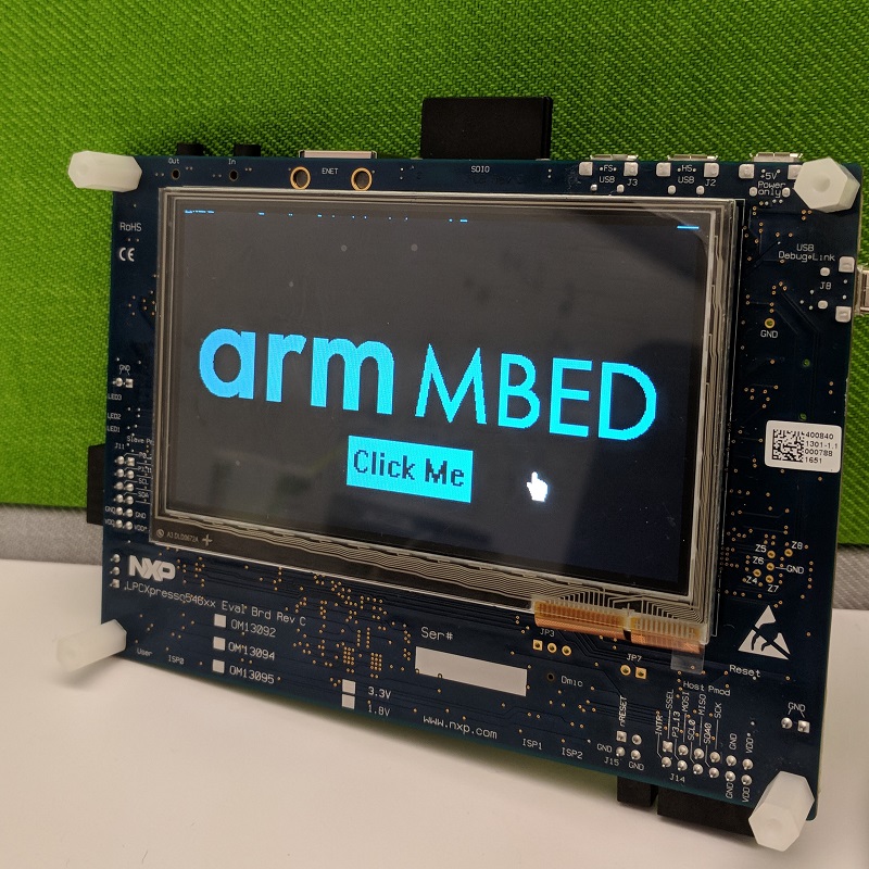
NXP Touch Cursor demo on a LPCXpresso54608
Pre-requisites
You will need to have the following software and equipment for this tutorial:
- Mbed CLI
- GCC ARM toolchain
- A serial terminal viewer (i.e.
screen, Tera Term, PuTTY, etc.) - LPCXpresso54608 board
Get NXP's example
First you will need to download NXP's example program:
- Navigate to NXP's example projects page
- Create an NXP account and sign in
- Select "GCC ARM Embedded" from the Toolchain dropdown
- Select "demo_apps"
- Select "touch_cursor"
- Click Download Example (then save the
touch_cursor.zipfile to your computer) - Extract the
touch_cursor.zipfile to a location on your computer.
Create a new Mbed OS project
- Create a new folder on your computer
- Open the folder's directory in your command-line
- Run
mbed new .
Then with your favorite text-editor, create a main.cpp file in the root of your new Mbed OS project.
Porting NXP's example to Mbed OS
In order to successfully compile and flash the touch cursor demo app to the LPCXpresso54608 board using Mbed CLI, we will need to make a few changes to the example code.
Copying the files
Within your extracted touch_cursor example folder, open the the file touch_cursor/source/touch_cursor.c. Copy the contents of this file into your Mbed OS project's main.cpp file.
We will also need to copy the following files to our Mbed OS project, copy and paste these files as-is from the touch_cursor directory to your Mbed OS project root folder:
touch_cursor/board/board.htouch_cursor/board/pin_mux.ctouch_cursor/board/pin_mux.htouch_cursor/touchpanel/fsl_ft5406.ctouch_cursor/touchpanel/fsl_ft5406.h
In order to compile these files as part of an Mbed OS project successfully, we will also need to change the extensions of all of the .c files above to .cpp.
Your Mbed OS project's root directory should now look like the following:
mbed-os/
board.h
fsl_ft5406.cpp
fsl_ft5406.h
main.cpp
mbed_settings.py
mbed-os.lib
pin_mux.cpp
pin_mux.h
Creating a safe printf
Because the NXP examples use a special "debug console", we will also need to create the following files within our Mbed OS project:
- Create a new file
stdio_thread.cppwith the following contents:
#include <stdarg.h>
#include <stdio.h>
#include "mbed.h"

#include "stdio_thread.h"

Mutex printf_mutex;

int safe_printf(const char *format, ...) {

    printf_mutex.lock();

    va_list args;
    va_start(args, format);
    int num_bytes = vprintf(format, args);

    va_end(args);
    printf_mutex.unlock();

    return num_bytes;
}
Also create a new header file stdio_thread.h with the following contents:
#ifndef __STDIO_THREAD_H__
#define __STDIO_THREAD_H__

int safe_printf(const char *format, ...);

#endif // __STDIO_THREAD_H__
This stdio_thread class allows for the safe usage of printf during the touch panel's touch event interrupts (i.e. to be able to print without overwriting the other simultaneous calls to printf).
Because we are no longer using NXP's fsl_debug_console.h, you will need to remove the #include statement for this header file at the top of fsl_ft5406.cpp (i.e. delete the line: #include "fsl_debug_console.h"). In addition to removing this #include statement, we will also need to add the following #include at the top of fsl_ft5406.cpp: #include "fsl_i2c.h" (this is so the touch panel code knows that we are going to use the I2C driver code present in the board's mbed-os/ directory).
Modifying main.cpp for Mbed OS
First we will need to update the included files at the top of our Mbed OS Project's main.cpp file. Change the #include statements to the following:
#include "mbed.h"
#include <stdio.h>
#include <string.h>
#include "stdio_thread.h"
#include "fsl_lcdc.h"
#include "fsl_ft5406.h"
#include "fsl_sctimer.h"
#include "fsl_gpio.h"
#include "fsl_i2c.h"
#include "image.h"
#include "board.h"
#include "pin_mux.h"
Next we will need to remove the following code (use find/replace to remove these items). Remove...
static uint8_t s_frameBufs[IMG_HEIGHT][IMG_WIDTH / APP_PIXEL_PER_BYTE];- The entire
APP_FillBuffer(void *buffer)method NVIC_EnableIRQ(APP_LCD_IRQn);BOARD_InitDebugConsole();- All references to
APP_FillBuffer
We will also need to redirect all PRINTF statements to our new safe_printf method. Use find/replace to change all calls to PRINTF with safe_printf. For example: change PRINTF("LCD init failed\n"); to safe_printf("LCD init failed\n");.
Search for GPIO_WritePinOutput and replace GPIO_WritePinOutput(GPIO, 2, 27, 1); with GPIO->B[2][27] = 1;.
Altering the demo
For this example we will be printing to the serial terminal whenever we click on the area defined by the blue "Click Me" button on the touch screen (see the picture at the beginning of the tutorial). In order to accomplish this we will need to alter the for loop within the main() function. Copy the following code and replace it over the entire for(;;) loop at the end of the main() function:
uint32_t xMin = 0xbd;
uint32_t xMax = 0xea;
uint32_t yMin = 0xb7;
uint32_t yMax = 0x12f;

for (;;)
{
    if (kStatus_Success == FT5406_GetSingleTouch(&touch_handle, &touch_event, &cursorPosX, &cursorPosY))
    {
        if ((touch_event == kTouch_Down) || (touch_event == kTouch_Contact))
        {
            /* Update cursor position */
            APP_SetCursorPosition(cursorPosY, cursorPosX);
            if (xMin < cursorPosX && cursorPosX < xMax && yMin < cursorPosY && cursorPosY < yMax) {
              safe_printf("You've clicked the button! (0x%2x, 0x%2x)\r\n", cursorPosX, cursorPosY);
            }
        }
    }
    else
    {
        safe_printf("error reading touch controller\r\n");
    }
}
The uint32_t variables before the for(;;) loop define the X and Y boundaries of the "Click Me" button shown in the "Arm Mbed" background image.
In order to show the "Click Me" image you will need to download the image.h file and save it to the root of your Mbed OS project. This header file is the "Arm Mbed" background image converted to a uint8_t array. This header file will be used by the LCD code to load up the LPCXpresso54608's current frame buffer with our Mbed logo and button image.
Note: If you are using the Arm Mbed image shown at the top of this tutorial and you would like the LCD screen to display the logo in the same blue color, towards the top of the main.cpp file look for the instantiation of a static const uint32_t palette[] variable and change it's value to: { 0x001F00000 }.
If you would like to use your own bitmap image for the LCD's background, you can create a 480x272 pixel Black and White bitmap image with an image editor such as Microsoft Paint. After you have created your image, within the editor, flip the image vertically (since Windows bitmap files are stored in reverse bit order, when you convert the bitmap to a hex array if it is not flipped before hex array conversion, the image will appear mirrored on the touch screen). Make sure to save the image as a "Monochrome Bitmap (*.bmp)" file. Then upload the bitmap file to Tomeko's file to hex converter, copy the output and replace the contents of image.h with this new array.
Note: You can also convert your bitmap image to a C hex array by opening it in the Vim editor and running the following command: :r !xxd -i yourfile.bmp.
If you use your own image, make sure to update the xMin, xMax, yMin, and yMax values with your new button boundaries. You can gather this X/Y information by printing out the following data during a touch event on your button's boundaries (within the for(;;) loop): safe_printf("0x%2x 0x%2x", cursorPosX, cursorPosY);.
Building the example
Within your command-line, navigate to your Mbed OS project directory. Make sure your LPCXpresso54608 is plugged into the computer. Compile and flash the program to your board with the following command: mbed compile -t GCC_ARM -m LPC546XX -f. Once the program has successfully flashed to the board, "reset" your board by pressing it's reset button or by unplugging it from your computer and plugging it back in.
Viewing the serial output
Earlier we altered our main() function's for(;;) loop to only print to the serial port when we have clicked on the area bounded by the "Click Me" button on the Arm Mbed image. In order to view these print statements, we will need to open up our serial terminal viewer.
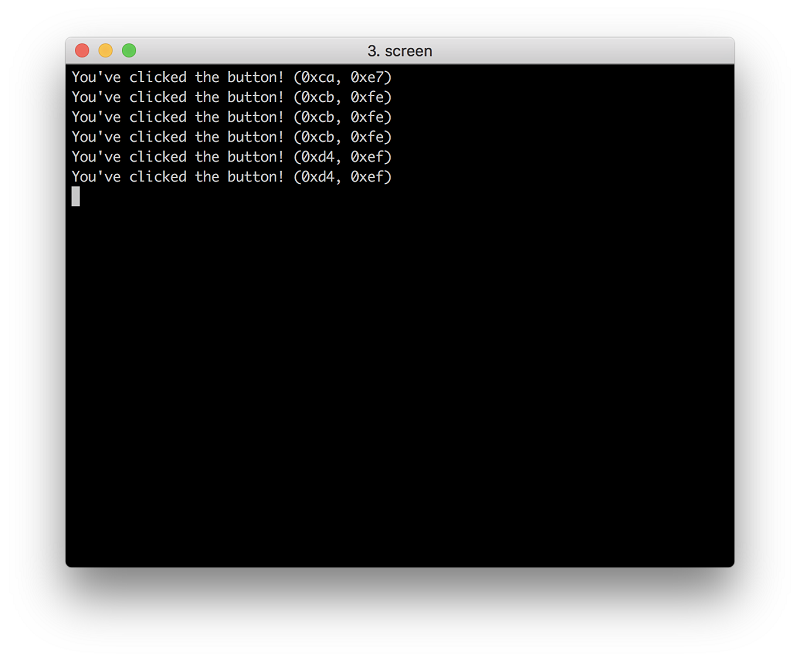
With your board plugged into your computer, open your command-line and run the following command within your Mbed OS project directory: mbed detect. This command will show you what serial port your board is connected to on your computer. Open up your serial terminal viewer to this port (I am using MacOS's screen on the command-line). Click on the touch panel's "Click Me" button and you should see similar output on your serial terminal viewer:

And you're done! The steps outlined in this tutorial can also be applied to many of the other examples available on NXP's website for use with Mbed OS.
