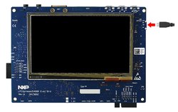
NXP LPCXpresso54608
LPCXpressoV3 development board for NXP LPC5460x processors
MCU Features
The LPC546xx MCU family combines the power efficiency of the Arm Cortex®-M4 core running at up to 220 MHz with multiple high-speed connectivity options, advanced timers, and analog features. DSP capabilities enable LPC546xx MCU devices to support complex algorithms in data-intensive application. Providing flexibility with up to 512 KB Flash and external memory interfaces, this family provides the ability to adapt as requirements change. Flash options support large, flexible internal and external memory configurations. Compatibility within the LPC54000 series enables the LPC546xx MCU family to provide a seamless migration path for increasing processing power and adding the flexibility of additional advanced peripherals.
- LPC54608ET512 Arm Cortex-M4 running at up to 180MHz
- 512 KB Flash
- 200 KB SRAM
- Flexible internal and external memory configurations
Board Features
The board is comprised of target LPC54608 device with an on-board, CMSIS-DAP / SEGGER J-Link compatible debug probe. The on-board probe is compatible with MCUXpresso IDE and other leading toolchains such as those from Keil and IAR. The board is also equipped with a standard 10-pin header enabling the use of 3rd party debug probes. In addition to standard LPCXpresso V3 features, this board includes a complete set of peripheral interfaces to enable developers to fully explore the capabilities of LPC5460x devices.
- 272x480 color LCD with capacitive touch screen
- On-board, high-speed USB, Link2 debug probe with CMSIS-DAP and SEGGER J-Link protocol options
- UART and SPI port bridging from LPC546xx target to USB via the on-board debug probe
- Support for external debug probe
- 3 x user LEDs, plus Reset, ISP (3) and user buttons
- Multiple Expansion options, including Arduino UNO and PMod
- Built-in power consumption measurement for target LPC546xx MCU
- 128 Mb Micron MT25QL128 Quad-SPI flash
- 16 MB Micron MT48LC8M16A2B4 SDRAM
- Knowles SPH0641LM4H digital microphone
- Full size SD/MMC card slot
- NXP MMA8652FCR1 accelerometer
- Stereo audio codec with line in/out
- High and full speed USB ports with micro A/B connector for host or device functionality
- 10/100 Mbps Ethernet (RJ45 connector)
- LPCXpresso54608/54618/54628 Onboard Sensors
- On-board Debug and Programming Interface Circuit with High Speed USB interface
- [USB MSC] Drag-n-drop programming
- [USB CDC] USB Serial Port
- [USB HID] CMSIS-DAP
Important Notes
Please note that support for the following features of LPCXpresso546xx are currently in development in Mbed OS. Schedule for release is TBD.
- LCD with capacitive touch screen
- High and full speed USB ports
- Quad-SPI flash
- SD Card
Signal Connection Information:
- D6, D7, A4, & A5 are not connected to the Arduino headers by default. See schematics for hardware modifications required to make the connections.
- Dx pins connected on the Arduino header do not support InterruptIn capability.
Board Pinout


The pinout diagrams above shows the commonly used interfaces and their locations.
Additional Pin Definitions
LEDs: LED_RED, LED1, LED2
SWITCHES: SW2, SW3, SW4, SW5
Firmware update required
Please make sure you have updated your LPCXpresso to the latest firmware to enable the mbed flash disk interface
Getting Started with mbed
1. Connect your microcontroller to a PC
Use the USB lead to connect your mbed to a PC. The status light will come on, indicating it has power. After a few seconds of activity, the PC will recognise the mbed Microcontroller as a standard USB drive.
 |  |
| Windows XP example | Mac OS X example |
2. Click the PRODINFO.HTM link to get logged in
Go to the new USB Drive, and click PRODINFO.HTM to open it in a web browser.
If you do not have an mbed account, choose "Signup", and create your mbed Account. Otherwise, log in with your normal username and password.
This will give you access to the website, tools, libraries and documentation.
PC Configuration
Your mbed Microcontroller can appear on your computer as a serial port. On Mac and Linux, this will happen by default. For Windows, you need to install a driver:
Windows
See Windows-serial-configuration for full details about setting up Windows for serial communication with your mbed Microcontroller
From a host PC to communicate with mbed you will need a terminal application. This allows the mbed Microcontroller to print to your PC screen, and for you to send characters back to your mbed.
- Terminals - Using Terminal applications to communicate between the Host PC and the mbed Micrcontroller
Some terminal programs (e.g. TeraTerm) list the available serial ports by name. However, if you do need to know the identity of the serial port so that you can attach a terminal or an application to it:
| Windows | Mac | Linux | ||||
| Find the identity of the COM port by opening ''Device Manager''. To do this navigate ''Start -> Control Panel -> System -> Hardware -> Device Manager''. | To find the device name under Mac OS X, use the command ''ls /dev/tty.usbmodem*'' | To find the device name under Linux, use the command ''ls /dev/ttyACM*'' | ||||
 |  |  |
Downloading A program
1. Save a program binary (.bin) to the Platform
Download the appropriate "Hello World!" binary:
- LPCXpresso54608: HelloWorld_lpcxpresso54608.bin
Note: the source code for this program will be seen in the next section.
Save the program binary file to your mbed Microcontroller Disk, just like you would with a normal USB disk. The Status LED will flash as the PC writes the file to the Microcontroller disk. The file is now consumed.
2. Press the Reset Button
When the Reset Button in pressed, the microcontroller will be reset and the last programmed application will begin to run.
3. Hello World!
The Microcontroller is now running the program; flashing LED1 forever! If you reset the Microcontroller, or disconnect and reconnect the power, the program will simply restart.

Open Existing Project
1. Import the Program to your mbed compiler
Select Import As Program
Choose Import Name of your preference
Click on Import
[Repository '/teams/mbed-os-examples/code/mbed-os-example-blinky/' not found]
2. Compile the Program
In the right panel Program Workspace Select the program you want to compile
Click on Compile in toolbar
If compilation ends successfully, you should see the comment Success! displayed in the Compile Output window available in the bottom and your web browser should download automatically the precompiled binary for the program.
3. Download a (.bin) to the Platform
Save the program binary file to your mbed Microcontroller Disk, just like you would with a normal USB disk. The Status LED will flash as the PC writes the file to the Microcontroller disk.
4. Press the Reset Button
When the Reset Button in pressed, the newest program on the mbed Microcontroller Disk will be loaded in to the Microcontroller FLASH memory. The Status LED will flash as this happens.
When the program is has been loaded onto the microcontroller, it will then start it running.
5. Run the Program
The Microcontroller is now running the program; flashing LED1 forever! If you reset the Microcontroller, or disconnect and reconnect the power, the program will simply restart.
Where Next
Learn more about Mbed OS APIs and tools, to help you create and deploy IoT devices
Technical Reference
Power
- Powered un USB or via Expansion connectors
- 3.3v regulated output on VOUT to power peripherals
- USB power available to slave USB devices with appropriate jumper settings (refer to use manual)
Schematics
Data Sheets
Interface Firmware

To compile a program for this board using Mbed CLI, use lpc546xx as the target name.
 Mbed Enabled
- Baseline
Mbed OS support
- Mbed OS 5.10
- Mbed OS 5.11
- Mbed OS 5.12
- Mbed OS 5.13
- Mbed OS 5.14
- Mbed OS 5.15
- Mbed OS 5.6
- Mbed OS 5.7
- Mbed OS 5.8
- Mbed OS 5.9
- Mbed OS 6.0
- Mbed OS 6.1
- Mbed OS 6.10
- Mbed OS 6.11
- Mbed OS 6.12
- Mbed OS 6.13
- Mbed OS 6.14
- Mbed OS 6.15
- Mbed OS 6.2
- Mbed OS 6.3
- Mbed OS 6.4
- Mbed OS 6.5
- Mbed OS 6.6
- Mbed OS 6.7
- Mbed OS 6.8
- Mbed OS 6.9
Example programs
CMSIS support
Find documentation, software examples and the CMSIS Board Support Pack.
NXP LPCXpresso54608 on keil.arm.com