HDMI-CEC Interface
Information
This is a concept for an HDMI-CEC Interface to control an AV Receiver that does not support HDMI. CEC is the low-speed communications protocol that traverses the HDMI interface and allows unified control of devices that are plugged in (TV, DVD players, AV Receivers, and so on).
Design Goals
The goal of this project is to interact via the HDMI port with modern equipment (TVs, DVD players, etc). This interaction has a few specific sub-goals of its own:
- Control a non-HDMI compatible AV Receiver (using RS-232) based on the HDMI-CEC Bus port commands. This includes:
- Turning the AV Receiver on and off,
- Controlling the AV Receiver volume level, and
- Switching the AV Receiver inputs to the appropriate source.
- Control the HDMI equipment remotely via the mbed. This includes basic commands like turning the TV on or off, changing the TV channel, and switching input sources on the TV. Possible means of control:
- Ethernet - web server or custom commands
- Bluetooth - from your handy phone/tablet
- RS-232 - interface to the AV Receiver
- IR Transceiver - use IR to control even more devices
- and more - the mbed has many communication possibilities.
Design Considerations
This design is intended to provide a simple interface to the CEC bus on an HDMI cable. Additionally, but with less attention to the details, the circuit supports the I2C link that is also on HDMI. It makes no attempt to deal with the high speed (Video and Audio) signals on HDMI. This device is an end-point, not a pass-thru.
Software Design Concepts
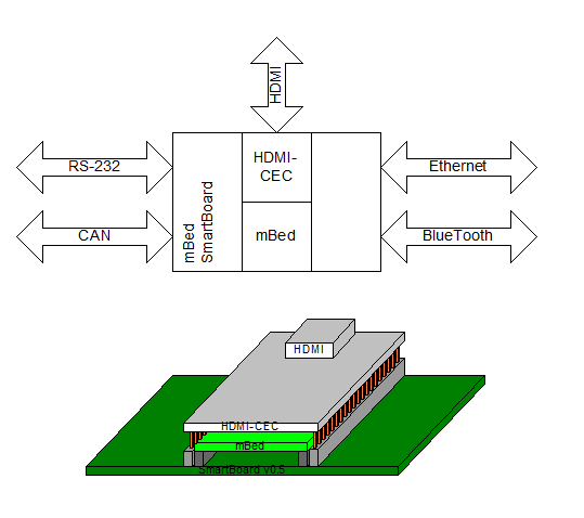
I'd like the interaction with the CEC-Bus to be one of several possible communication paths, so it can "bridge" different interfaces.
This design has now [20120701] been built but not yet tested. It is presented to open discussions on this topic, see what others may have already learned, and hopefully refine the concepts into a successful build.
Schematic
It's a pretty simple schematic, as you see here or in the downloadable PDF.
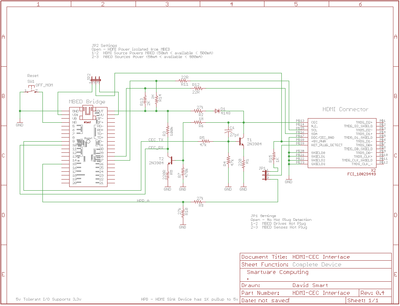
It follows the pattern from some other sites, with a few component values changed based on the analysis I did using LTC Spice.
Spice Schematic
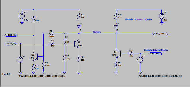
The left side of this schematic is the same basic schematic shown above, however this version was entered into LT Spice. The right side of this version simulates another device on the CEC interface.
Spice Waveforms
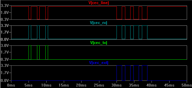
In analyzing the waveforms from the LT Spice analysis, you can see good signals in all cases. Another pair of eyes would be helpful, but this appears to satisfy the electrical requirements of CEC communications.
PCB Design
An earlier version of this was single sided, and could have been produced in the home lab, but this version opted for a few more features and a ground plane to help manage EMI. With this change, it became a double-sided PCB.
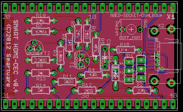
Aside from the rather fine-pitch HDMI interface (which may present some challenges), all other parts are intentionally thru-hole to make assembly in your home lab easier. Care must be taken to solder the HDMI connector first, and the remaining in whatever order makes it convenient. There are further suggestions below.
The PCB layout is intended to "bridge" over top of an mbed, which is itself plugged into one of the many baseboards (e.g. SmartBoard Baseboard or others) that provide two rows of pins.
Order this PCB
1 Jun 2012: Parts are on order, but I have not yet built this design. So, while every attempt has been made to produce a working design and an accurate BOM, please review the information carefully.
Build with HDMI-CEC v0.4
28 Jun 2012: The PCBs arrived. Here's my progression of the build. Since it is a pretty simple circuit, hopefully not much will go wrong (except as you see in the first step).
Handy Tools:
- Solder Paste
- Solder Wick
- Fine time soldering iron
- Small diameter solder
- A steady hand
- A good magnifier (an inexpensive eye loupe works well)
- A small bench vise to hold the PCB
Recommended Construction Sequence:
- Hole sizes for the PCB stand-off connectors are too small. They should have been larger for the 0.025 sq post stand-offs. I had to drill them out and used a 0.035 in drill. This was still "snug", but it was what I had handy. Drilling these out affects three plated through holes that connect to pins on the bottom side. These will need special handling to reflow some solder to them (pins 1, 15, 40).
- HDMI Connector:
- CAUTION: The leads are small - do not drag your soldering iron across the leads or you may bend them causing bridging to adjacent pins.
- Spread a little solder paste across all the top-side pads for this connector.
- Set the connector down on the PCB and check that its pins are not bent and line up into the paste.
- Solder all the pins. If you have a steady enough hand, you may be able to skip the next couple of steps. If you're more like me, there was a lot of bridging of two or more pins.
- Lay a fresh end of the solder wick across the bridged pins and heat it up with the iron. It will draw off the excess solder, ideally leaving no bridges.
- If any bridges remain that won't come clean, add a little more solder to them first, and be sure to use a fresh end of the solder wick.
- Inspect the connections very carefully now, because with other components in place you won't have access to touch these up again.
- Turn the board over and solder the 4 hold-down pins on the HDMI connector
- Install the reset switch. One switch was hard to solder in, until I realized there was a lot of oxidation on its leads. I gently scraped all 4 sides of each lead until they were shiny, then had no problems.
- Install C1. Depending on the capacitor lead forming, you may need to watch that it does not bridge from one lead to the via that is between the two holes for C1.
- Install everything else except the stand-off connectors at the edge of the board. Remember, this design was intentionally using leaded components for easier home assembly. Just be sure to double-check the component values before soldering them down.
- Recommendation is to install 3 or 4 parts at a time, gently flair their leads just enough to hold them in place, turn the board over, solder and then clip the excess leads.
- Repeat with the next few parts.
- Install the stand-off connectors on the bottom side, so the top side of the PCB stands up tall (the long leads are sticking down below the board. If you do not seat the connector fully onto the board, it may be easier to perform that extra soldering step on pins 1, 15, and 40.
- On the top-side, the stand-off connector pins should be just barely stickup up above the PCB. Make sure they are of uniform height before you start soldering.
- Solder each of the pins on the top-side.
- Turn to the bottom side, and carefully heat and solder pins 1, 15, and 40. Take extra care with 1 and 40, since these two could easily get out of alignment with the rest of the pins.
Hardware Checkout
Now that it is built, I first plugged it into a breakboard, so I could perform just a few basic checks that it is working correctly.
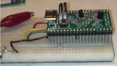
With this simple configuration, I could drive the transmit pin and monitor the CEC bus levels. Similarly, I could drive the CEC bus and monitor the receive pin levels. All was good.
Bridge HDMI-CEC v0.4 over top of SmartBoard v0.05
Some of the same pins that the HDMI-CEC interface uses to communicate with the mbed are also used by peripherals on the SmartBoard, so a few of the shunt / jumpers must be removed. See the following table to see which to remove.
| Pin | HDMI-CEC Feature | Changes on SmartBoard |
|---|---|---|
| 1 | Ground | No changes needed |
| 2 | V input | HDMI-CEC JP2: 1-2 to power from the HDMI interface |
| 4 | Reset | No changes, reset on HDMI-CEC same as mbed |
| 9 | CEC-Tx | SmartBoard JP11: Pin 1 must be not shunted |
| 10 | CEC-Rx | SmartBoard JP12: Pin 1 must be not shunted |
| 15 | HDMI Plug Detect | SmartBoard AIN0: No change (100K pulldown on v0.05) |
| 27 | CEC SCL | SmartBoard JP10: disconnect shunt |
| 28 | CEC SDA | SmartBoard JP8: disconnect shunt |
| 39 | V input (alternate) | No changes needed |
| 40 | Power for CEC BUS | No changes needed (provides power to HDMI-CEC |
Then, it is ready to install as a bridge over the mbed on the SmartBoard.
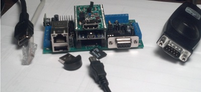
Changes for the Future Version
- Enlarge holes for stand-off connectors
- Add test points on the PCB for CEC-Bus and other key signals
Software
For this, I have just about nothing so far - aside from research and a few concepts. Here, perhaps, this community can provide the greatest benefit. And the mbed site will soon (as of mid-June 2012) have collaboration capability.
What I do have:
- A few SW architecture drawings to help me see what I want to create
- A heavily modified version of the cec-arduino (see below) software that compiles and runs under Visual Studio C++ Express 2010, including simulating messages on the CEC Bus. (Passenger side of a long drive). I also took the offline ARM compiler along, but it doesn't yet build in that environment.
External References
- cec-arduino
- HDMI organization where you can access the HDMI spec
- Andrew Carr's site
Comments and Feedback are Encouraged
If you've thought about this, done anything about it, or thinking of doing something, I'd like to hear from you. Please comment on this page.
Please log in to post comments.
