Pinball Machine using MBED
We built a pinball machine in MBED using parts and devices from previous labs.
Current features:
- 2 DC Motors powered by a 9V battery to control the flippers to maneuver the pinball.
- A Solenoid powered by a 12V DC power supply to launch the pinball initially.
- A pinwheel powered by a 5V battery holder and a RC Servo used as an obstacle on the playing field
- 3 5-way tactile switches (not connected) embedded into the playing board to act like bumpers
- An IR sensor used to track pinball movement. 2 LEDs light up when ball passes through each of the 2 IR sensors. An additional IR sensor is used on the bottom of the board to detect "game over" state.
- A TextLCD (2x16) screen is used to display 3 different states:
- Display the start screen until the solenoid launches the pinball and starts the game.
- Display the score while the game is active.
- Display the game over screen when the ball reaches the bottom of the playing field.
- A speaker was used that plays a sounds when pinball reaches "Game Over" state (pinball is detected by IR sensor on bottom of game board)
Hardware
IR Sensor
Reference Notebook: https://os.mbed.com/users/4180_1/notebook/ir-and-rf-remote-controls/
Link for IR Receiver/LED wiring: https://learn.sparkfun.com/tutorials/ir-control-kit-hookup-guide
Instead of using the breakout board, we found it easier to work directly with the IR LED and IR Receiver, as it was easier to mount to the playing field. The wiring is similar to the one in the notebook, and we also use the trick of connecting the cathode of the IR LED to a Serial TX pin so we can use the Serial API functions getc and putc to send data over IR transmission.
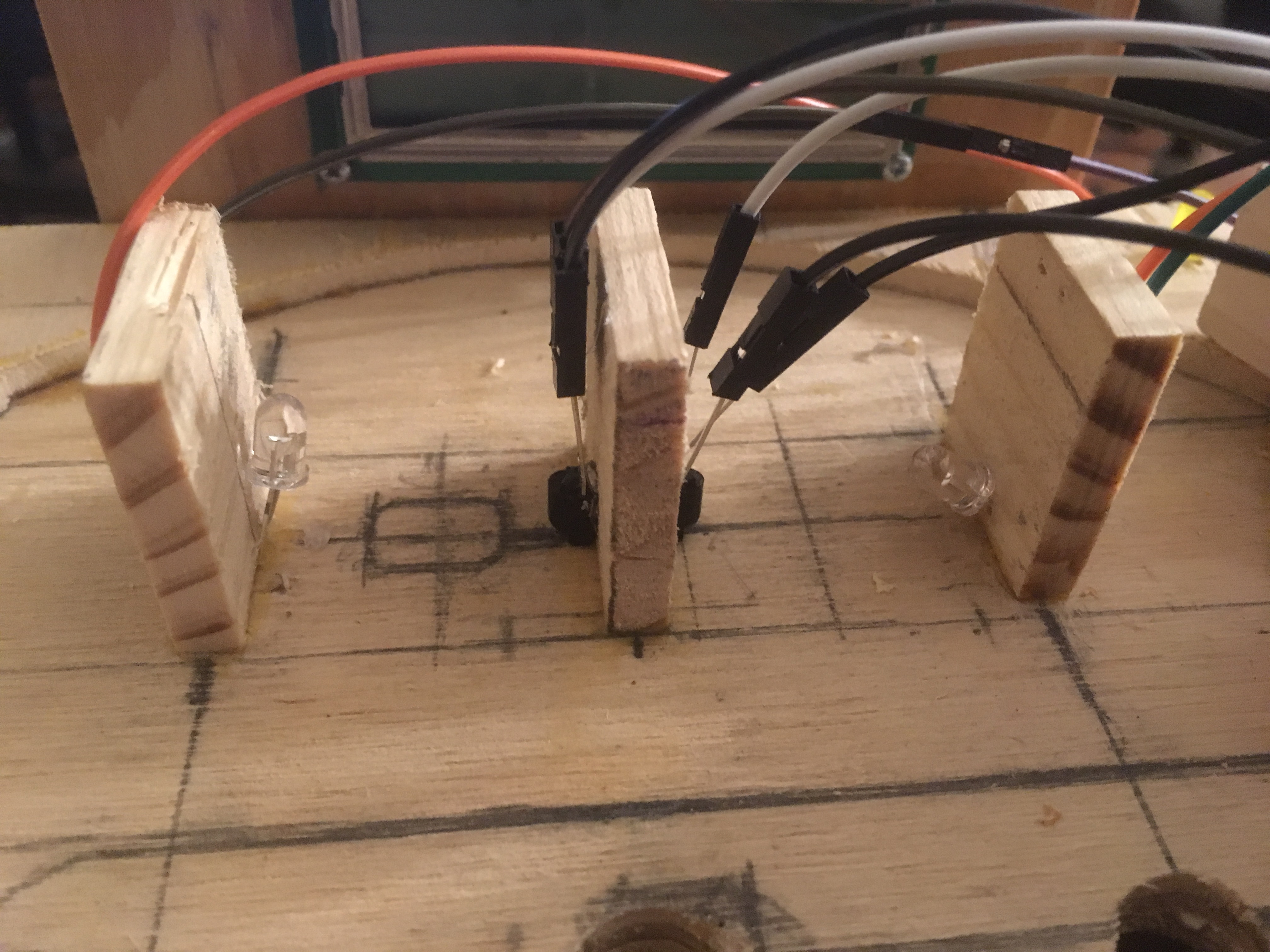
The IR LEDs were fixed onto a thin piece of wood by drilling 2 small holes for the anode and cathode, and then putting the 2 through the hole and securing the other side of the LED, angling it so the LED is facing the receiver (similar to an L shape). This is done so the LED is always facing the IR transmitter and thus is always transmitting to it. When the pinball comes between the LED and the receiver, the receiver shouldn't be receiving anything (essentially the opposite of Serial.readable()) and can be detected easily. This is how we detect if the ball has passed through our 2 makeshift parallel wooden walls. When this happens, a yellow LED lights up, showing the player that the pinball has accomplished this. When the pinball passes through both sides (ie both LEDs light up), the player gets 1000 points, and can repeat the same thing over and over again. To summarize there are 3 parallel pieces of wood, on the 2 ends there are 2 IR LEDs fixed in an L shape and in the middle there are 2 IR receivers on both sides glued on upside-down. The 3 parallel pieces of wood are glued onto the playing board.
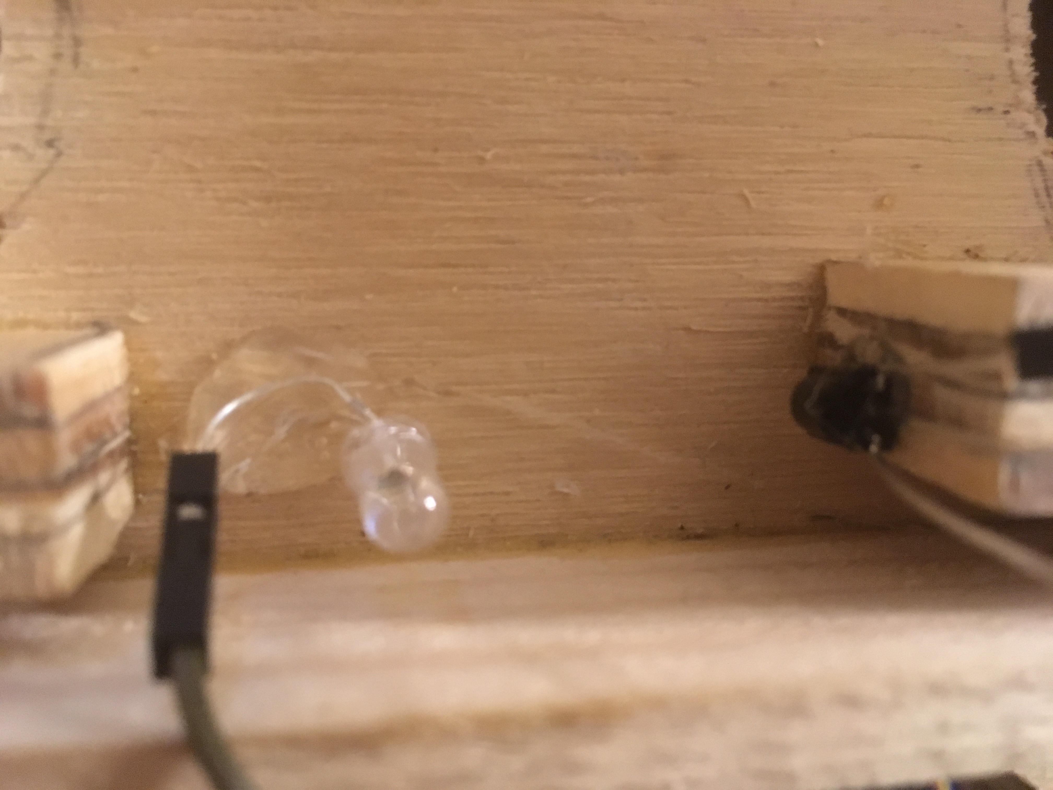
On the bottom of the board for detecting game over, we didn't have a parallel piece of wood so we just glued the IR LED onto the playing field itself and angled it in the shape of a U, and the IR receiver facing it upside down.
We have 3 total pairs of IR LEDs and receivers. 2 of them are used for detection the pinball moving through the parallel wooden walls at the top of the playing board and the other one is used for detecting when the pinball reaches the bottom of the playing board (game over). The wiring for all 3 pairs is very similar, because there are a total of 3 Serial tx/rx pins on the mbed, each is used for a pair.
Wiring
| mbed | IR LED | IR receiver |
|---|---|---|
| gnd | gnd (Pin 2) | |
| VU (5V) | Vs (Pin 3) | |
| Serial TX pin (pin 9, 13, or 28) | Cathode | |
| Serial RX pin (pin 10, 14, or 27) | Out (Pin 1) | |
| pin 21 (or some other PwmOut pin) | Anode |
Information
Make sure you have a resistor in series with the Anode of the IR LED to the PwmOut pin (pin 21). 330 ohms should work best.
Yellow LEDs
Reference notebook: https://os.mbed.com/users/4180_1/notebook/rgb-leds/
2 yellow LEDs were used along with the IR sensor/receiver to show the user when the pinball passes through the left or right side of parallel walls on the top of the playing field. When both sides are passed through, both LEDs light up, the player gets 1000 points, and then the LEDs turn off, allowing the player to do the same thing again. Currently this is the only way for the player to get points. The 2 LEDs were fastened to the top corners of the playing field, one on the left and one on the right side. Small holes were drilled through the wood so the LED's anode and cathode could go through the wood and be wired to the mbed inside.
Resistors
Resistors were placed in series with P5/P6 and to the anode of the LED so it doesn't short and burn out. 330 ohm resistors were used.
| mbed | Left LED | Right LED |
|---|---|---|
| P5 | Anode | |
| P6 | Anode | |
| GND | Cathode | Cathode |
DC Motor
Motor Datasheet: https://www.alibaba.com/product-detail/36JX30K-36ZY85P-12V-Micro-DC-Planetary_591865475.html
This is a 12V Micro DC Planetary Gear Motor. We used a DC motor of this size because we needed a long shaft to place our flippers. This DC motor also has a high voltage rating, so putting in i.e. 9V of power would give our flippers enough force to flick the ball.
Note
The main reason we are choosing to use DC motors and not a solenoid to power our flippers is because we tested out the force outputted by a solenoid (20 V one) and it barely moved our ball. These DC motors gave us more than enough power for our ball, and we didn't even max out the voltage.
We need a PWM input to our 2 motors, so we can use a SparkFun Motor Driver - Dual TB6612FNG. The motor supply (VM) is limited to a maximum voltage of 15VDC, and the output current is rated up to 1.2A per channel, but we only need 0.7A.
Wiring
| mbed | H-Bridge | 9V Power Supply | Motors |
|---|---|---|---|
| VMOT | + | ||
| GND | GND | - | |
| A01 | Right Motor - | ||
| A02 | Right Motor + | ||
| B01 | Left Motor + | ||
| B02 | Left Motor - | ||
| P17 | AIN1 | ||
| P18 | AIN2 | ||
| P19 | BIN1 | ||
| P20 | BIN2 | ||
| P21 | PWMA | ||
| P22 | PWMB |
Note
Make sure you wire the leads of the 2 motors to the correct input, to ensure that your motor flips towards the bottom of the game board, and not the top.
Since we are making a pinball game, we only want to power our motors when the button is pressed, so we wire 2 pushbuttons as AnalogIns to our MBED using the PinDetect library:
| mbed | pushbuttons |
|---|---|
| p7 | left motor button |
| p8 | right motor button |
Solenoid
Solenoid from Adafruit: https://www.adafruit.com/product/412
We used a solenoid as a launcher for our pinball since it was a good force-and-release mechanism . However, the solenoid we did needed a very large current and also needed a large voltage to power it (12 V).
Note
Make sure you use the proper power supply for your solenoid, i.e. don't use 9V batteries for a 12V solenoid. You can get away with putting multiple 9V batteries in parallel to reduce the current through each battery, but if possible try and use a 12V power supply for the best results.
We also want to use a pushbutton here to release our solenoid (apply 12V across it) when we press the button and launch our pinball into our game board.
Wiring
| solenoid | 12V power supply | push button |
|---|---|---|
| + | one side of pushbutton | |
| + | other side of pushbutton | |
| - | - |
We essentially want to connect one of the leads of our solenoid to one side of the switch and have the 12V of our power supply on the other side of the switch so pressing down on the switch applies the 12V to our solenoid. Then we connect the other lead of the solenoid to ground.
Servo
MBED notebook for servo: https://mbed.org/cookbook/Servo
Here we are going to use a servo to power a pinwheel to act like an obstacle in our pinball game. In general, servos only spin up to 180 degrees. However, they can be modified to spin a full 360 degrees, and we need one since we want our pinwheel to make full rotations.
To design the pinwheel, take a block of wood and cut it until you get the shape of a square cross, with the dimensions being 1.25 in length by 0.25' in width by 0.25' in depth. Then screw a hole in the center of the cross and connect the screw to the servo.
Picture:
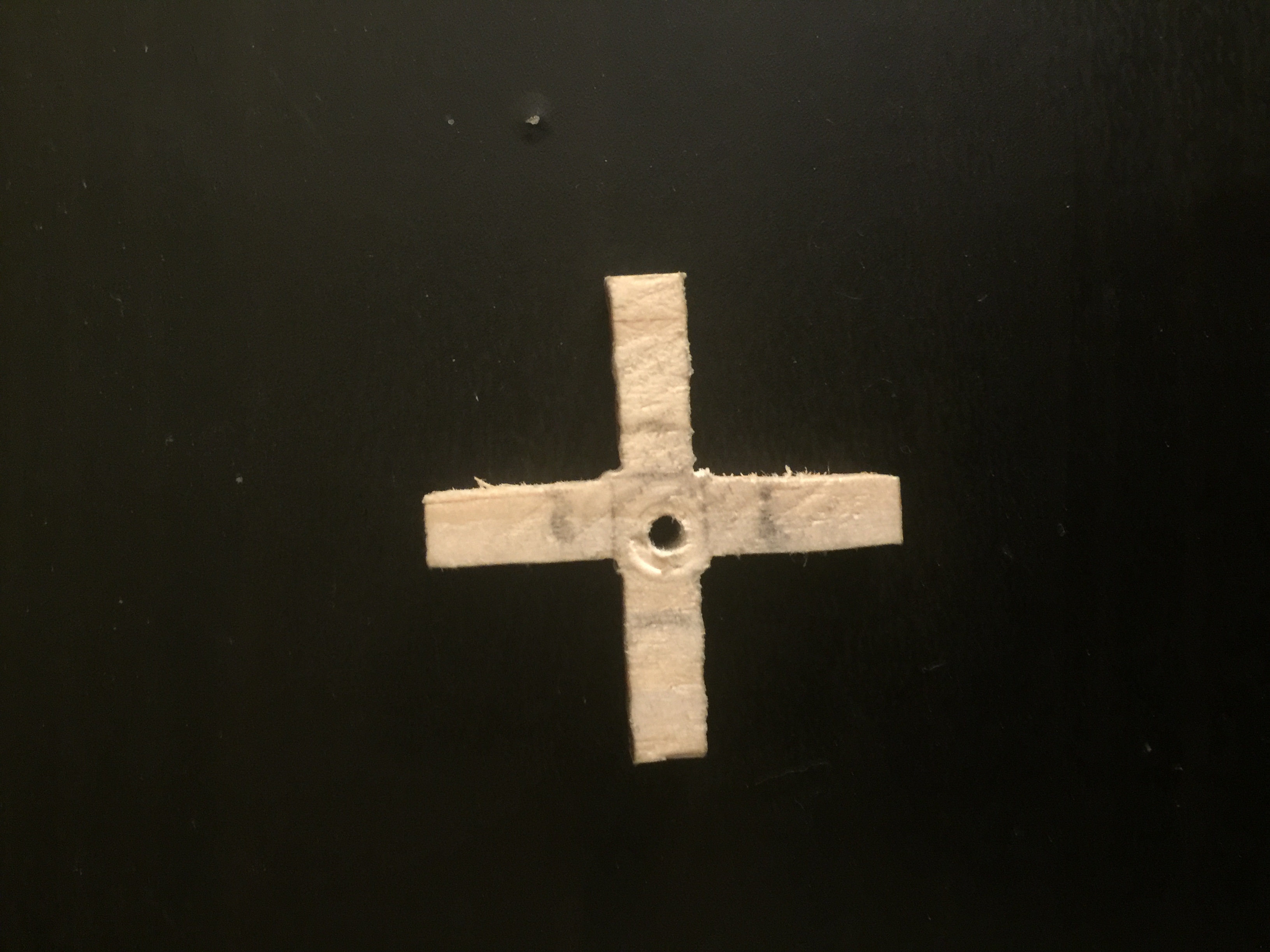
Now, servos need between 4.5V - 6V of power, so we are going to use an external battery pack with a barrel jack adapter. You can also use a 5V AC Adapter that plugs into a wall socket.
Wiring
| mbed | Servo | 5V power supply |
|---|---|---|
| VIN (red) | + | |
| GND | GND (black) | - |
| P21 | PWM (yellow/white) |
Important note about programming the servo: Even if you manage to get a servo that rotates a full 360 degrees, since the servo only accepts PWM value from 0.0. to 1.0, inclusive. When we initially set a PWM value for our servo (i.e. 0.0) and set another PWM value after, the servo will rotate in one direction until that PWM value is reached. So, in order to get the servo spinning in the same direction (and not back and forth), we need to do a hack shown below:
getting a servo to rotate the same direction continuously
#include "mbed.h"
#include "Servo.h"

Servo myservo(p21);

int main() {
    while(1) {
        myservo = 0.0;
        wait(0.5);
        myservo = -1.0;
        wait(0.5);
    }
}
As you can see in the example code, we set a PWM signal of -1.0 after initially setting our Servo to 0.0. Since -1.0 isn't a valid PWM value for our Servo, it will continue to rotate in one direction until that PWM value is reached because it thinks it can be reached (even though it cannot).
LCD Screen
Reference Notebook: https://os.mbed.com/users/wim/notebook/textlcd-enhanced/
The LCD used is a TextLCD (2x16). The specific one used is a Lumex 801602 D/A. The datasheet for that LCD can be found here: https://www.lumex.com/spec/LCM-S01602DSR+A.pdf. The LCD uses the HD44780 dot matrix liquid crystal display driver/controller, for which a datasheet can be found here: https://www.sparkfun.com/datasheets/LCD/HD44780.pdf. Normally displaying characters on the LCD involves using 8-bit registers and placing small black dots in a matrix like fashion, which is complicated and takes a while. Thankfully in the notebook linked above there's a TextLCD library that makes displaying strings on the LCD as simple as using printf, which simplifies the work we need to do. It was mounted (using screws) to a thin piece of plywood, and a long hole was drilled to allow the header pins to go through the plywood. The plywood was glued (using wood glue) to the top of the box at the end of the playing field. It represents the scoreboard for the game and shows player's score. For wiring, we directly connected the pins to the mbed using a parallel bus. There are other ways to connect the TextLCD as described in the linked notebook.
Import libraryTextLCD
Updated for more display types. Fixed memoryaddress confusion in address() method. Added new getAddress() method. Added support for UDCs, Backlight control and other features such as control through I2C and SPI port expanders and controllers with native I2C and SPI interfaces. Refactored to fix issue with pins that are default declared as NC.
Wiring
| TextLCD | mbed |
|---|---|
| p1 GND | GND |
| p2 VCC | VU (5V) |
| p3 VO | via wiper of 10k pot |
| p4 RS | p15 |
| p5 RW | GND |
| p6 E | p16 |
| p7 D0 | not connected |
| p8 D1 | not connected |
| p9 D2 | not connected |
| p10 D3 | not connected |
| p11 D4 | p17 |
| p12 D5 | p18 |
| p13 D6 | p19 |
| p14 D7 | p20 |
Contrast Voltage (VO)!
Pin 3 (VO) of the TextLCD is connected to the middle pin of a 10k pot. This is because the pin has a different behavior on different types of TextLCD displays. The 10k pot should be wired as follows: one pin to Vcc (3.3V), other to GND, and the middle pin to Pin 3 of the TextLCD. More info here: https://os.mbed.com/components/Potentiometer/. The 10k pot should be adjusted until you see a top line of solid rectangles, then back off until they just disappear.
5-way navigation switch
Reference notebook: https://os.mbed.com/users/4180_1/notebook/using-a-navigation-switch-digital-joystick/
Exact product on Adafruit: https://www.adafruit.com/product/504
This is more of an optional part, but the original idea was for the pinball game was to have three 5-way navigation switches to act like bumpers, where the pinball would move fast and hard enough to move the switch in some direction (Up, Left, Down, or Right). The problem was that the pinball we used was too light and weak to move the switches at all, so we left them in the board to act like bumpers that don't really do anything.
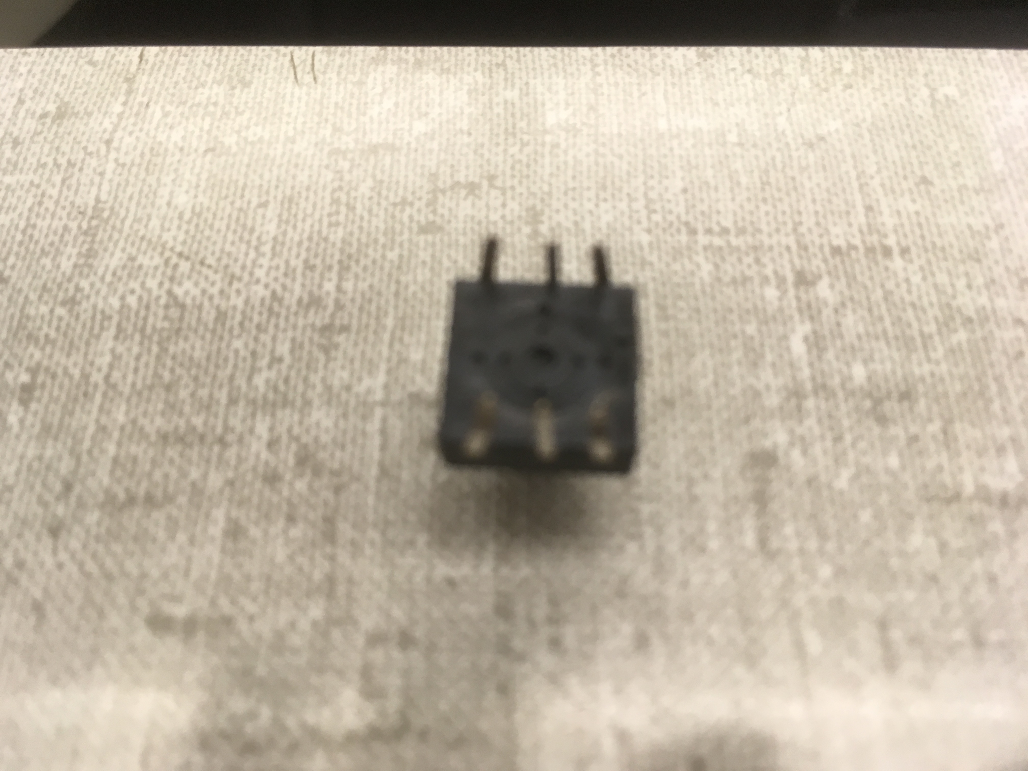
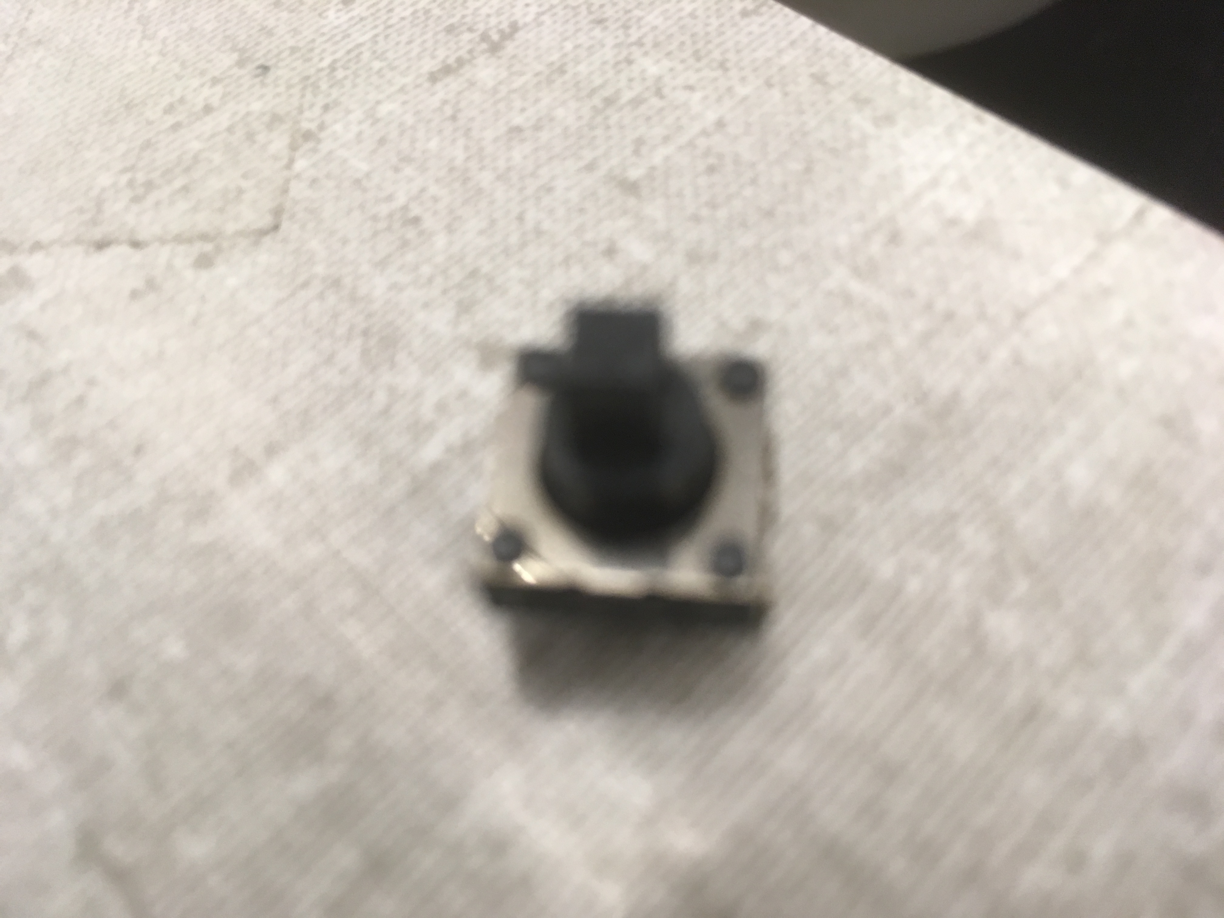
There's no wiring diagram for the exact product on the Adafruit page, but for a similar one. Nevertheless, the wiring is mostly the same. In the picture above, the "bottom" of the switch is the part with the small rectangular slit (which can be kind of seen on the right side of the bottom of the switch). Using that as the "bottom" of the switch, in the left "bottom" corner is Pin 3, and in the right "bottom" corner is Pin 4.
Wiring
| 5-way navigation switch | mbed |
|---|---|
| Pin 4 | GND |
| Every other pin | Some DigitalInput pin |
There are 5 other pins other than the common ground, which represents the 5 different ways the switch can be pressed. When the switch is pressed, a 0 will be read. You can connect all 5 of the pins to the same DigitalInput pin, or all 5 of the pins to different DigitalInput pins. For pinball, we think it would make the most sense for the 5 pins to be connected to the same DigitalInput pin (like p5), as it doesn't matter how the switch is pressed, just that the switch is pressed.
We left the code for handling the switches being pressed in our code, although in our case it will never be executed. The 3 switches had all 5 pins connected to one DigitalInput pin, and those pins were p7, p8, and p11. The switches were placed into the board by taking a 1/2 inch drill bit and drilling a large circular hole into the board, and then the switch was hot glued into the hole, ensuring that the top of the switch is level with the rest of the wood so the pinball can move smoothly across it.
Speaker
Reference notebook: https://os.mbed.com/users/4180_1/notebook/using-a-speaker-for-audio-output/
We used a speaker along with the Class D Audio Amplifier to play a short tune when it's game over. We used the PlayNote function from the Speaker.h class in the following code. Timer interrupts seemed to mess with the serial communication and the IR transmissions, so we stayed away from it.
Import programspeaker_demo_PWM
Demo for new class to play a note on a speaker using a PWM output See http://mbed.org/users/4180_1/notebook/using-a-speaker-for-audio-output/
Wiring
| mbed | TPA2005D1 (Class D Audio Amp) | Speaker |
|---|---|---|
| gnd | pwr - (gnd), in - | |
| Vout (3.3V) | pwr+ | |
| p25 (any PWM or D/A) | in + | |
| out+ | + | |
| out - | - | |
| Any DigitalOut px(optional) | S (low for shutdown) |
Assembly
In this section I will cover what sizes of wood to cut and glue appropriately to build the pinball apparatus. I label the parts using a letter and break down the assembly into sections.
Box
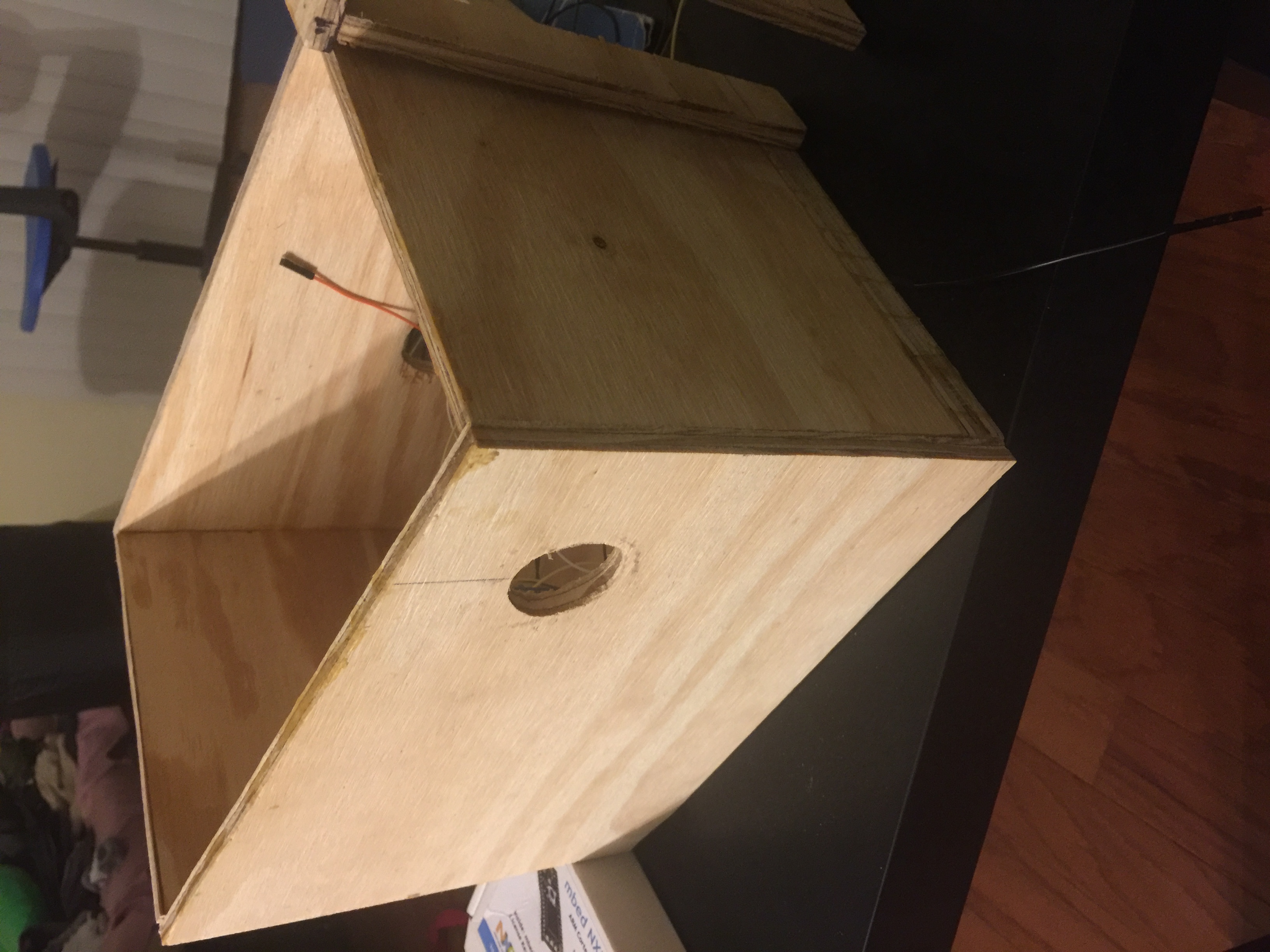
First, we build the Box, or base of our machine. We will place our game board on top of our box and the mbed and wire connections inside this box.
Parts:
- Parts A & B: Trapezoids with dimensions: Length: 11 inches; Width: 0.25 inches; Depth 1: 8 inches; Depth 2: 7 inches
- Part C: Box with dimensions: Length: 11 inches; Width: 7 inches; Depth: 0.75 inches
- Part D: Box with dimensions: Length: 0.25 inches; Width: 7 inches; Depth: 6.25 inches
- Part E: Box with dimensions: Length: 0.25 inches; Width: 7 inches; Depth: 7.25 inches
Assembly:
- Connect parts A and B to part C with part C on the bottom.
- Connect part D between parts A and B on 7 inch side
- Connect part E between parts A and B on 8 inch side
Result:
Solenoid Launcher
Next, we build the solenoid launcher for the pinball in front of part D in the "Box" section.
Parts:
- Parts F & G: Boxes with dimensions: Length: 1.25 inches; Width: 0.25 inches; Depth: 7 inches
- Part H: Box with dimensions: Length: 2.5 inches; Width: 1.25 inches; Depth: 0.25 inches
Assembly:
- Connect part F on right edgeof part D in "Box" Section
- Connect part H on top edge of part F
- Connect part G underneath on bottom edge of part H
Result:

Game Board
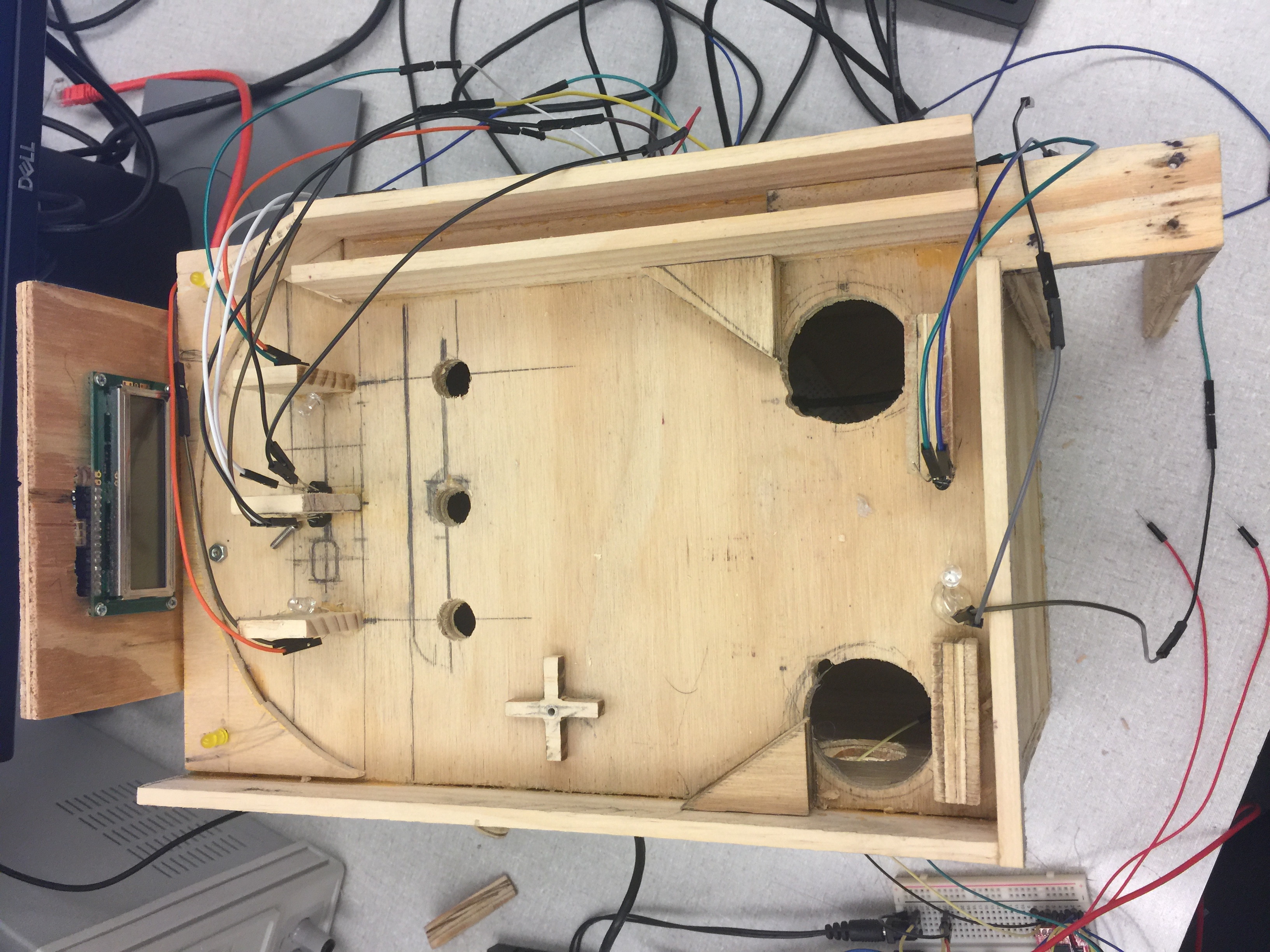
For the game board, we didn't make exact measurements we just pieced parts as we saw fit. Be creative with the board and use devices as you see fit.
Here is a picture of our game board, without the devices added in:
Demo
Below is a video demonstration of our pinball machine with the Yellow LEDs lighting up every time the pinball passes through the IR sensor.
Code
Code for the project can be found below.
2 MBEDs were used for this project. One MBED controls motors (motor driver to DC motors, Servo, buttons). The other MBED controls LCD Screen, IR sensors, and speaker. This allows the motors to run at maximum power and ensure the sensor readings are accurate and able to detect pinball motion.
MBED #1 Code:
It uses the TextLCD and mbed libraries. It handles the IR sensors, LEDs, Speaker, TextLCD, 5-way Nav Switch, and pinball game logic and scoring.
Import programMBED_Pinball_4180_final_project
Code for Pinball game using MBED for ECE 4180 final project.
MBED #2 Code:
It uses the Motor, PinDetect, Servo and mbed libraries. It handles the DC motors, Servo, and respective buttons to power the motors.
Import program4180_Final_Project_Motors
motor portion of pinball project for ECE 4180 Final Project
Please log in to post comments.


