Robotics for Cat and Mouse with mbed
Team NEST
Justin Eng, Ganesh Subramaniam ECE 4180 Final Design Project, Spring 2014
Import programRoboticsCatAndMouse_HumanDriver
Spring 2014, ECE 4180 project, Georgia Institute of Technolgoy. This is the human driver (RF controller) program for the Robotics Cat and Mouse program.
Import programRoboticsCatAndMouse_AutonomousDriver
Spring 2014, ECE 4180 project, Georgia Institute of Technolgoy. This is the autonomous driver program for the Robotics Cat and Mouse program.
Overview

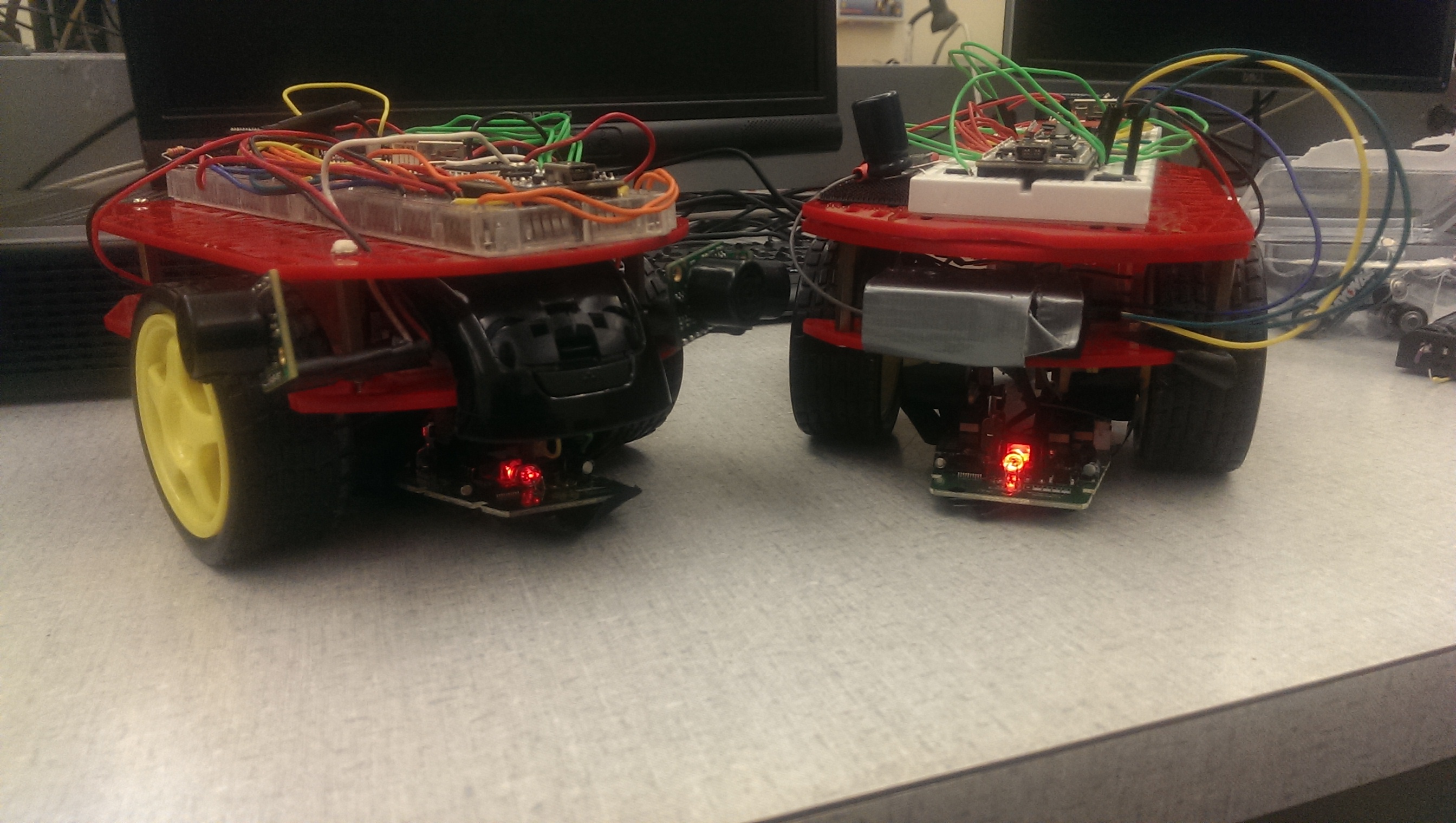
The objective of this project is to implement a robotic version of "Cat and mouse." The "Cat and Mouse" construct has one player chase the other until tagged. For this project, there will be two robotic cars utilizing the mbed lpc1768: a user car, and autonomous car. The user car will be controlled by a human via an RF remote control, while the second car will be completely autonomous. The implemented version explained below has the user car chase the autonomous car, until the user is close enough to the autonomous car to register a "tag." The following hardware was required:
Hardware Common to Both Cars
- mbed lpc1768
- Magician CHassis (https://www.sparkfun.com/products/10825)
- 6.4V Power Supply (we used 4 AA batteries)
- Wireless Xbee Module (https://www.sparkfun.com/products/11215)
- Accelerometer/Gyroscope Combo board (https://www.sparkfun.com/products/10121)
- Dual H-Bridge Stepper Motor Driver (http://www.pololu.com/product/1182)
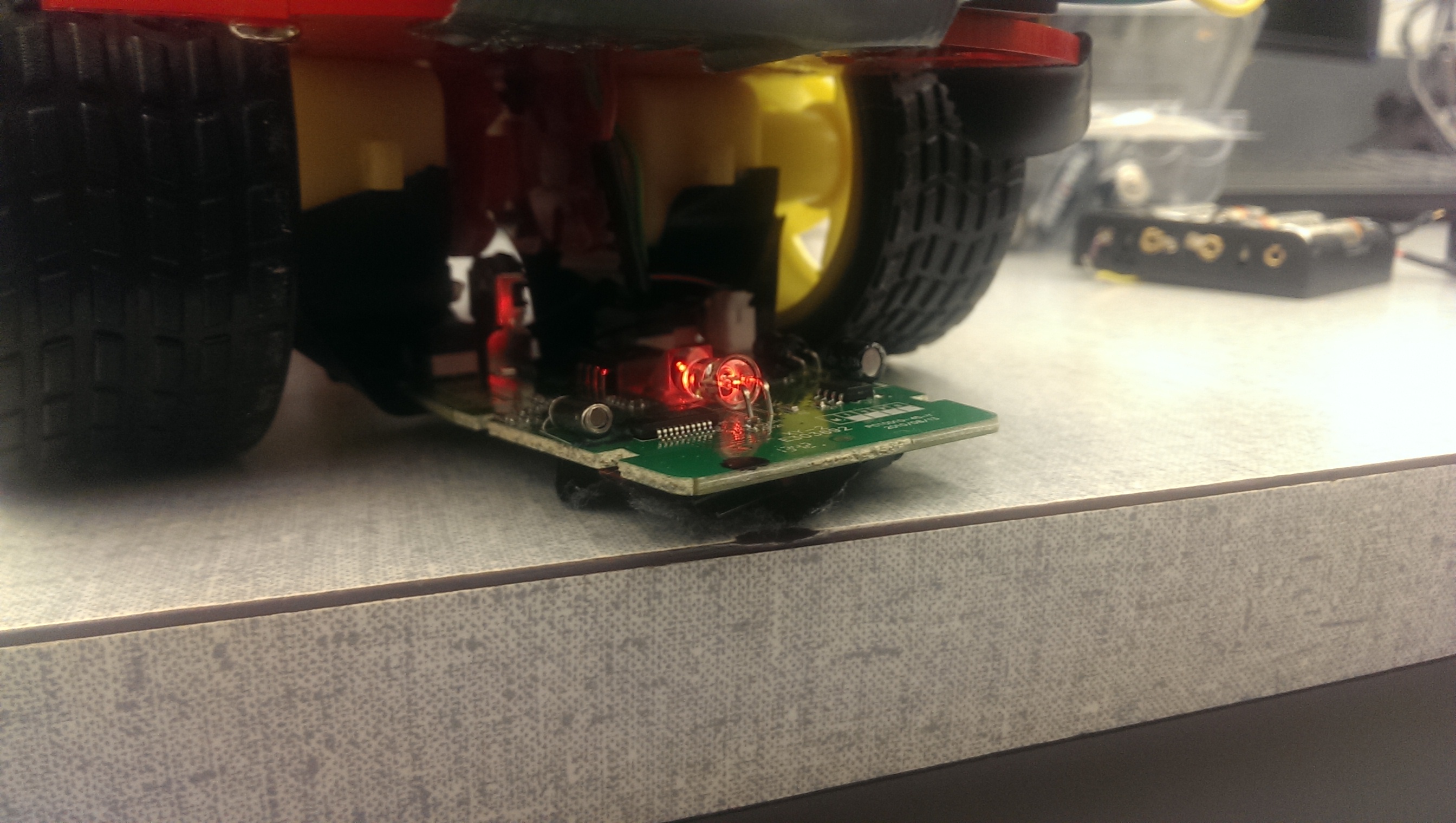
- Optical Sensor (We used the optical sensor from a wireless mouse, http://www.target.com/p/ge-mouse-wireless-optical-mini/-/A-13631608#prodSlot=medium_1_27&term=mouse)
- Female USB Breakout (for mouse interface, https://www.sparkfun.com/products/12700)
Specific to User Car
- RF Transmitter and Receiver Module (http://www.ebay.com/itm/like/231201322369?lpid=82)
Specific to Autonomous Car
- Three Sonar Sensors (https://www.sparkfun.com/products/8502)
Video
A quick demonstration of a working implemntation. First, the autonomous car will have a 10 second head start to get some distance between itself and the user car. After this 10 second window, a human will use an RF remote controller to navigate the user car towards the autonomous car while the autonomous car attempts to flee. A tag will be evident when both cars stop and the mbed leds begin to flash a pattern.
Note, USB cables are attached for power only (the car's batteries were beginning to die).
Device Explanation and Wiring
Devices Common to Both Cars
Accelerometer/Gyroscope
The accelerometer and gyroscope is an IMU combo-board which uses I2C. This combo board gives us 6 degrees of freedom and allows us to use intensive IMU filtering with the IMUFilter mbed library from the mbed cookbook. The products from the filter, specifically the getYaw(), produce a stable orientation value relative to 0, ranging from 0 to +179 and 0 to -179. The orientation is necessary in order to assist calculations with the xy positioning from the optical sensor as well as calibrating the motors to drive in a relative straight path.
This is a video of the magician autonomous car driving straight with the assistance of the accelerometer/gyroscope and its IMU filtering.
It is important to note that before deferring to the accelerometer/gyroscope, both a compass and the optical sensor were used individually. However, due to too much electromagnetic interference and instability while the car was moving resulted in the compass being dis-guarded. For the optical sensor alone, dozens of custom filters ranging from low-pass and high-pass filtering and average filtering were tried to reduce the static values at idle and account for the overall accumulative error. It was found that the optical mouse sensor we used was terribly overprecise, where the number of samples and sample values were too inconsistent in order to use regression analysis to obtain orientation based on it's x and y outputs. In the end, the accelerometer and gyroscope with the IMU filtering proved to be the most stable, reliable and consistent tool in order to determine the orientation of the robot. Below is the wiring for the IMU combo board.
| Mbed Pin | Pin |
|---|---|
| Vout | Vcc |
| GND | GND |
| I2C SCL, p10 | SCL |
| I2C SDA, p9 | SDA |
Female USB Breakout
The USB breakout was necessary to interface with the optical sensor from a wireless mouse. The IC surface mounted chip was removed from the wireless mouse casing, along with's its 2 AA battery power supply. The 2 AA power supply used a two pin molex connector to supply the optical sensor with power, while the wireless dongle was attached to the usb breakout connector. In software, we used the USBHostMouse library within the human interface devices (HID) to obtain code that will generate an interrupt with the status of each button and the x/y position change of the mouse every time an event occurs.

The mouse's original intention was to calculate the car's x and y coordinate positions. To reduce error, the same model mouse was mounted on each car. As stated in the Accelerometer/Gyroscope section, the optical mouse was proven to be a insufficient device to solely determine the car's orientation. However, the the accleremotoer/gyroscope's orientation, simple trigonometry allowed the delta y of the USBHostMouse interrupts to determine the cumulative x and y position. Below is the wiring for the USB breakout, and also the interrupt code to generate the cumulative x and y position.
| Mbed Pin | Pin |
|---|---|
| VU | 5V |
| GND | GND |
| D+ | D+ |
| D- | D- |
Cumulative X & Y Coordinate Calculations using Trigonometric Interpolation
void onMouseEvent(uint8_t buttons, int8_t x_mickey, int8_t y_mickey, int8_t z)
{
    // mouse movements are in mickeys. 1 mickey = ~230 DPI = ~1/230th of an inch
    double y_temp = y_mickey / 232.6 * 100;
    double g_temp = imuFilter.getYaw();

    // determine direction we are facing and add to that direction
    double dx = 0;
    double dy = 0;
    QUADRANT quadrant;
    if (toDegrees(g_temp) > 0 && toDegrees(g_temp) <= 90)
        quadrant = FORWARD_LEFT;
    if (toDegrees(g_temp) < 0 && toDegrees(g_temp) >= -90)
        quadrant = FORWARD_RIGHT;
    if (toDegrees(g_temp) > 90 && toDegrees(g_temp) <= 180)
        quadrant = BACKWARD_LEFT;
    if (toDegrees(g_temp) < -90 && toDegrees(g_temp) >= -180)
        quadrant = BACKWARD_RIGHT;

    switch (quadrant) {
        case FORWARD_LEFT:
            dy = y_temp * cos(g_temp);
            dx = -y_temp * sin(g_temp);
            break;
        case FORWARD_RIGHT:
            dy = y_temp * cos(g_temp);
            dx = -y_temp * sin(g_temp);
            break;
        case BACKWARD_LEFT:
            dy = -y_temp * sin(g_temp);
            dx = y_temp * cos(g_temp);
            break;
        case BACKWARD_RIGHT:
            dy = y_temp * sin(g_temp);
            dx = -y_temp * cos(g_temp);
            break;
    }

    // add to total position
    x_position += dx;
    y_position += dy;
   ...
}
Wireless XBee
The mechanisms for the user car to tag the autonomous car is via proximity. The user car needs to transmit it's current x and y position to the autonomous car so that the autonomous car can check if the user car is within the dead zone range to be considered tagged. This is where the Xbees come in. Each car has an Xbee which implement a custom protocol.
The user car will transmit it's x and y position every quarter of a second, and the autonomous car will spin and wait for a transmission. Once a packet is received, the autonomous car will do a bounds check to determine if the game is over. If so, the autonomous car will transmit back a byte to the user car. This will be the only instance where the autonomous car transmits anything. The user car will check for a readable byte, and if received, will begin executing it's game over code. If it is not game over, then the autonomous car will just wait for the next packet from the user car, and the user car will continue to send it's x and y position every quarter second.
The x and y positions are stored as doubles (4 bytes) in each car's program, but only the integer value will be transmitted. The specific packet structure for sending and reading requires that a single byte be transmitted at a time. Thus the specific protocol for sending the x y position is as follows:
- Send ascii code for 'x'
- Send 8 MSB, or the MSByte of x position
- Send next MSByte.
- Send next MSByte.
- Send next MSByte.
- Repeat 1 through 5 for y position and ascii code for 'y'.
For the autonomous car to send the game over signal back to the user car, it really can write anything to the buffer. For this project, we write the ascii code for 'd' to the buffer 500 times as a sanity check to make sure the byte is received successfully.
Below is the wiring for the xbee as well as the send and receive code to implement this protocol.
| Mbed Pin | Xbee Pin |
|---|---|
| Vout | Vcc |
| GND | GND |
| Serial Rx, p15 | Dout |
| Serial Tx, p14 | Din |
| p16 | RST |
Example demo using the Xbees with our custom protocol.
Sending an XY coordinate via XBee
void sendPosition(void const *)
{
    // temp variables
    int x = 0;
    int y = 0;
    char a = 0;
    char b = 0;
    char c = 0;
    char d = 0;

    // sample current xy position
    x = (int) x_position;
    y = (int) y_position;

    pc.printf("Sending: %d %d...\n\r", x, y);

    // break down x coordinate by byte
    a = x >> 24;
    b = x >> 16;
    c = x >> 8;
    d = x;

    // put each byte on the buffer
    xbee.putc('x');
    xbee.putc(a);
    xbee.putc(b);
    xbee.putc(c);
    xbee.putc(d);

    // break down y coordinate by byte
    a = y >> 24;
    b = y >> 16;
    c = y >> 8;
    d = y;

    // put each byte on the buffer
    xbee.putc('y');
    xbee.putc(a);
    xbee.putc(b);
    xbee.putc(c);
    xbee.putc(d);

    pc.printf("Send complete.\n\r");

    // wait for a possible game over response
    wait(0.25);
    if(xbee.readable() && xbee.getc() == 'd') {
        gameOver = true;
        pc.printf("gameOver Received!\n\r");
        endGame();
    }
}
Receiving an XY coordinate via XBee
void receivePosition(void const *)
{
    // temp variables
    char buffer[SERIAL_BUFFER_SIZE];
    int index = 0;
    int xt = 0;
    int yt = 0;

    // wait for start character
    while(xbee.readable() && xbee.getc() != 'x' && !gameOver);

    // receive data packet of size PACKET_SIZE bytes
    pc.printf("Receiving...\n\r");
    index = 0;
    while(index < PACKET_SIZE && !gameOver) {
        if(xbee.readable())
            buffer[index++] = xbee.getc();
    }
    buffer[index] = NULL;

    // reassemble data
    xt = buffer[1];
    xt = xt << 8;
    xt = xt | buffer[2];
    xt = xt << 8;
    xt = xt | buffer[3];
    xt = xt << 8;
    xt = xt | buffer[4];
    x_hum = (double) xt;

    yt = buffer[6];
    yt = yt << 8;
    yt = yt | buffer[7];
    yt = yt << 8;
    yt = yt | buffer[8];
    yt = yt << 8;
    yt = yt | buffer[9];
    y_hum = (double) yt;

    pc.printf("Recieve complete: %d, %d\n\r", (int) x_hum, (int) y_hum);
}
6.4V External Power Supply
The External Power supply is required in order to drive the Magician Chassis's two DC motors. This is because the mbed's 5V VU USB Out can safely handle only 4mA. The motors require at least 7mA to function correctly. For this project, 4 AA batteries at 1.4V each wired in series were used as the external power supply. Below is the wiring for the external power supply:
| Mbed Pin | Pin |
|---|---|
| Vin | + of Power Supply |
| GND | - of Power Supply |
Dual-H-Bridge
The dual-H-Bridge is used to take in the external power supply and feed the two DC motors on the magician Chassis. Below is it's wiring.
| Mbed Pin | Pin |
|---|---|
| +P.S. | Vcc |
| GND | GND (all) |
| PWM, p21 | PWMB |
| PWM, p22 | PWMA |
| p23 | Ain1 |
| p24 | Ain2 |
| p25 | Bin1 |
| p26 | Bin2 |
Device Explanation and Wiring Specific to User Car
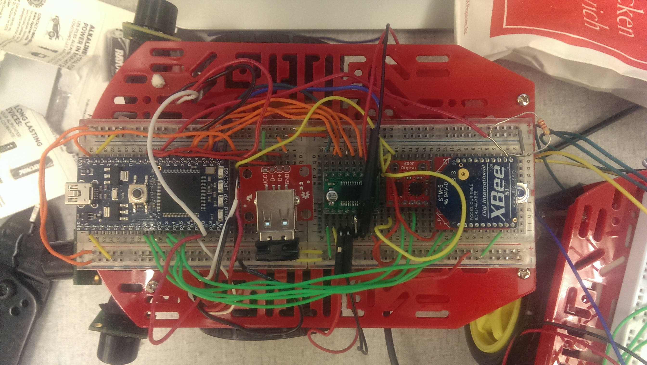
Example wiring for user car:

RF Transmitter and Receiver Module
| Mbed Pin | Pin |
|---|---|
| +3.3V | +V Rail |
| GND | GND |
| p11 | Channel 1 PWM Signal |
| p12 | Channel 2 PWM Signal |
The user car is directly controlled by the human. To accomplish this a 2.4 GHz radio receiver was used in conjunction with an RC flight controller. The RF receiver has independent PWM outputs for each control axis on the RC controller (Right stick X and Y). The mbed uses a captive waiting loop in conjunction with a timer to implement PWM reads, and acquire the stick value on the controller. This is then passed to a control algorithm which drives the motors according to user input.
Example demo of the user car being controlled by the RF remote controller and receiver.
int getRadioY()
{
    Timer timer;
    timer.reset();
    int dur;
    while(!elevator && !gameOver);
    timer.start();
    while(elevator && !gameOver);
    dur = timer.read_us();
    return dur;
}
Device Explanation and Wiring Specific to Autonomous Car
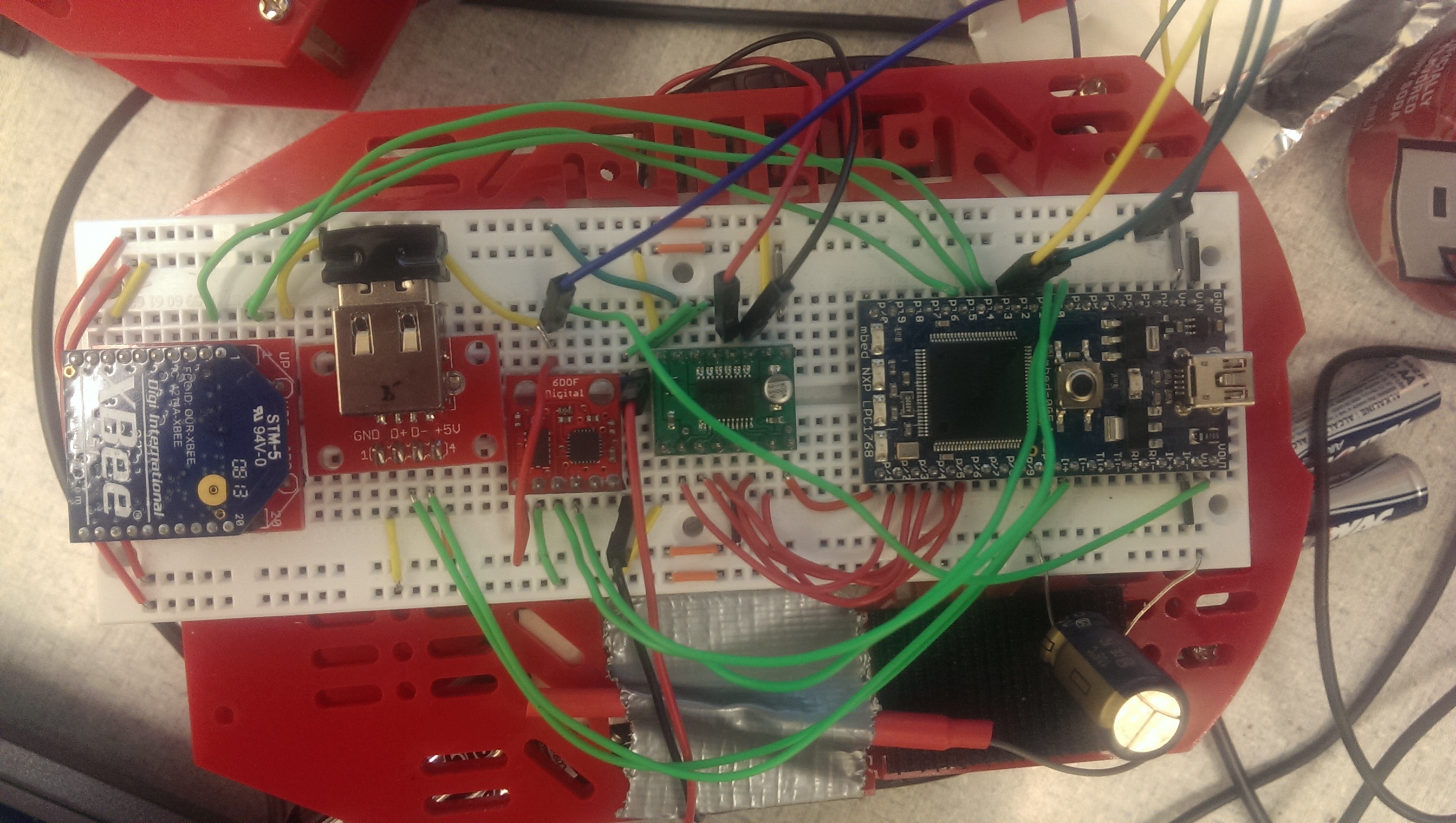
Example wiring for autonomous car:

Sonar Sensor
In order to implement collision detection for the autonomous car, three sonar sensors were attached to the front of the Magician Chassis. Each sensor was scaled to provide a value in the range of 0 to 10 where any read value less than 1.8 (approximately 6 inches) is considered an obstacle. The collision detection system will first check for an obstacle in the front center. If detected, it will determine whether the left or right center has more distance. Based on the sensor with the lesser distance, the car will turn itself towards that direction until the sensor on the opposite side shows no obstacles.
For example, if the center sensors shows an obstacle, the autonomous car will stop. If the left sensors shows a lower value than the right sensor, the robot will turn right until the left sensors is pointing in a direction where it does not detect an obstacle any more, and the center sensors shows the same.
Below is the pin configuration for the sonar sensors.
| Mbed Pin | Pin |
|---|---|
| Vout | Vcc (all) |
| GND | GND (all) |
| AnalogIn, p17 | Left Sonar |
| AnalogIn, p16 | Center Sonar |
| AnalogIn, p18 | Right Sonar |
Example of the sonar sensors driving the collision detection system.
1 comment on Robotics for Cat and Mouse with mbed:
Please log in to post comments.

Excellent project, very useful.