Important changes to repositories hosted on mbed.com
Mbed hosted mercurial repositories are deprecated and are due to be permanently deleted in July 2026.
To keep a copy of this software download the repository Zip archive or clone locally using Mercurial.
It is also possible to export all your personal repositories from the account settings page.
Dependents: IoTWorkshopLCD IoTWorkshopBuzzer IoTWorkshopSensors C027_USSDTest ... more
Fork of C027 by

Revision 20:89c45165ee87, committed 2014-05-09
- Comitter:
- mazgch
- Date:
- Fri May 09 11:25:28 2014 +0000
- Parent:
- 19:61d31c12230d
- Commit message:
- Remove pinlist (is now part of the platform)
Changed in this revision
diff -r 61d31c12230d -r 89c45165ee87 C027.cpp
--- a/C027.cpp	Mon May 05 15:44:46 2014 +0000
+++ b/C027.cpp	Fri May 09 11:25:28 2014 +0000
@@ -3,27 +3,10 @@
 *   http://mbed.org/platforms/u-blox-C027/
 *
 */
-#if defined(TARGET_UBLOX_C027) || defined(TARGET_LPC1768)
-
- #include "C027.h"
+#if defined(TARGET_UBLOX_C027)

-#if !defined(TARGET_UBLOX_C027)
-// override the mbed_die function
-void mbed_die(void)
-{
-    DigitalOut led(LED);
-    __disable_irq();
-    for (;;)
-    {
-        // nothing to do here
-        led = 0;
-        wait_ms(200);
-        led = 1;
-        wait_ms(200);
-    }
-}
-#endif
-
+#include "C027.h"
+
 C027::C027() :
     // Modem
     mdmEn(MDMEN, 0),            // LDO off
diff -r 61d31c12230d -r 89c45165ee87 C027.h
--- a/C027.h	Mon May 05 15:44:46 2014 +0000
+++ b/C027.h	Fri May 09 11:25:28 2014 +0000
@@ -8,19 +8,10 @@

 #include "mbed.h"

-#if !defined(TARGET_UBLOX_C027) && !defined(TARGET_LPC1768)
+#if !defined(TARGET_UBLOX_C027)
   #warning "this library is indended to be used only with the C027 board"
 #else

-#if !defined(TARGET_UBLOX_C027)
-  // if not native we are using the pin definition file from this library
-  #include "C027_PinNames.h"
-  // we also need to override the mbed_die function
-  void mbed_die(void);
-#else
-   // on the native platform the pins are already defined
-#endif
-
 //#define C027_REVA // select this define if you use revision A boards.

 /** C027 Helper class to control the power supply and interface
diff -r 61d31c12230d -r 89c45165ee87 C027_PinNames.h
--- a/C027_PinNames.h	Mon May 05 15:44:46 2014 +0000
+++ /dev/null	Thu Jan 01 00:00:00 1970 +0000
@@ -1,129 +0,0 @@
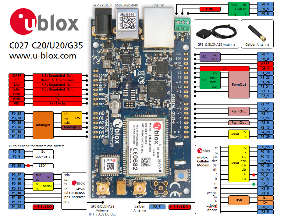
-/*  Platform header file, for the u-blox C27-C20/U20/G35
-*   mbed Internet of Things Starter Kit
-*   http://mbed.org/platforms/u-blox-C027/
-*
-*   Defines for pin connections of the LPC1768
-*/
-
-#pragma once
-
-#ifndef TARGET_UBLOX_C027
-
-// u-blox MAX-7Q GPS/GLONASS receiver
-// http://www.u-blox.com/gps-modules.html
-// -----------------------------------------------------------
-// I2C (shared with LISA/SARA)
-#define GPSSDA      (P0_27)
-#define GPSSCL      (P0_28)
-#define GPSADR      (66<<1) // GPS I2C Address
-// UART
-#define GPSTXD      (P0_10)
-#define GPSRXD      (P0_11)
-#define GPSBAUD     9600    // Default GPS Baud Rate
-// Control
-#define GPSRST      (P1_18) // Reset (input to GPS, active low)
-#define GPSPPS      (P1_19) // 1PPS Timepulse (output from GPS)
-#define GPSINT      (P1_22) // Interrupt (input to GPS)
-#define GPSEN       (P1_29) // Supply Control (high = enabled)
-
-// u-blox LISA/SARA cellular modem
-// http://www.u-blox.com/wireless-modules.html
-// -----------------------------------------------------------
-// UART (LPC1768 = DTE, LISA/SARA = DCE)
-#define MDMTXD      (P0_15) // Transmit Data
-#define MDMRXD      (P0_16) // Receive Data
-#define MDMCTS      (P0_17) // Clear to Send
-#define MDMDCD      (P0_18) // Data Carrier Detect
-#define MDMDSR      (P0_19) // Data Set Ready
-#define MDMDTR      (P0_20) // Data Terminal Ready (set high or use handshake)
-#define MDMRI       (P0_21) // Ring Indicator
-#define MDMRTS      (P0_22) // Request to Send (set high or use handshake)
-#define MDMBAUD     115200  // Default Modem Baud Rate
-// USB (not available on C27-G35)
-#define MDMUSBDP    (P0_29) // USB D+
-#define MDMUSBDN    (P0_30) // USB D-
-#define MDMUSBCON   (P2_9)  // USB Connect
-#define MDMUSBDET   (P0_7)  // USB Detect (n/a on REV.A board)
-// Control
-#define MDMEN       (P2_5)  // Supply Control (high = enabled)
-#define MDMPWRON    (P2_6)  //
-#define MDMGPIO1    (P2_7)  // GPIO1, Network status
-#define MDMRST      (P2_8)  // Reset (active low, set as open drain!)
-#define MDMLVLOE    (P0_9)  // Serial/GPIO Level Shifter Output Enable (n/a on REV.A board)
-#define MDMILVLOE   (P0_8)  // I2C Level Shifter Output Enable (n/a on REV.A board)
-
-// PIN header connector
-// for standard-based form factor with expansion board
-// -----------------------------------------------------------
-// PMW  = Pulswidth Modulator
-// EINT = External Interrupt
-// AOUT = Analog Output
-
-// Analog Ports (A0-A5)
-#define A0          (P0_23) //      I2S_CLK
-#define A1          (P0_24) //      I2S_WS
-#define A2          (P0_25) //      I2S_SDA
-#define A3          (P0_26) // AOUT
-#define A4          (P1_30) //
-#define A5          (P1_31) //
-// Digital Port (D0-D7)
-#define D0          (P4_29) //      TXD
-#define D1          (P4_28) //      RXD
-#define D2          (P2_13) // EINT
-#define D3          (P2_0)  // PWM
-#define D4          (P2_12) // EINT
-#define D5          (P2_1)  // PWM
-#define D6          (P2_2)  // PWM
-#define D7          (P2_11) // EINT
-// Digital Port (D8-D13)
-#define D8          (P2_4)  // PWM
-#define D9          (P2_3)  // PWM
-#define D10         (P1_21) // PWM  SSEL
-#define D11         (P1_24) // PWM  MOSI
-#define D12         (P1_23) // PWM  MISO
-#define D13         (P1_20) // PWM  SCK
-//      GND
-//      AREF
-#define SDA         (P0_0)
-#define SCL         (P0_1)
-
-// LED
-// -----------------------------------------------------------
-#define LED         (P3_25)  // RED LED (n/a on REV.A board)
-
-// CAN (TJA1040)
-// -----------------------------------------------------------
-#define CANRD       (P0_4)
-#define CANTD       (P0_5)
-#define CANS        (P0_6)  // standby (low=normal, high=standby/rxonly)
-
-// Ethernet (DP83848)
-// -----------------------------------------------------------
-#define ETHTXD0     (P1_0)
-#define ETHTXD1     (P1_1)
-#define ETHTXEN     (P1_4)
-#define ETHCRS      (P1_8)
-#define ETHRXD0     (P1_9)
-#define ETHRXD1     (P1_10)
-#define ETHRXEN     (P1_14)
-#define ETHREFCLK   (P1_15)
-#define ETHMDC      (P1_16)
-#define ETHMDIO     (P1_17)
-#define ETHOSCEN    (P1_27)
-#define ETHRST      (P1_28)
-#define ETHLINK     (P1_25) // LED_LINK
-#define ETHSPEED    (P1_26) // LED_SPEED
-
-// mbed / debug IF (LPC11)
-// -----------------------------------------------------------
-// Serial Port
-#define USBTXD      (P0_2)  // identical USBTX
-#define USBRXD      (P0_3)  // identical USBRX
-// ISP port
-#define ISP         (P2_10)
-
-// Reserved / NC pins
-// -----------------------------------------------------------
-#define RSVD2       (P3_26)
-
-#endif
\ No newline at end of file
