Important changes to repositories hosted on mbed.com
Mbed hosted mercurial repositories are deprecated and are due to be permanently deleted in July 2026.
To keep a copy of this software download the repository Zip archive or clone locally using Mercurial.
It is also possible to export all your personal repositories from the account settings page.
Fork of non-os_oss by
HW_Config
Hardware configuration
Sensor daughter board
Put each sensor daughter board to the appropriate place. Some combo sensor (e.g. Accelerometer & Gyroscope) are designed to fit one of them. All daughter boards have 15 pins and are divided into 7 and 8. Please carefully check the place of No.1 pin and the number of pins. Then you will find the right place.
In the sample source code, Magnetometer is defined as CONFIG_SLOT1, Accelerometer is defined as CONFIG_SLOT2, Gyroscope is defined as CONFIG_SLOT3.

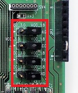
Choose power supply level
You can choose each sensor's power supply voltage and interface signal level. When jumper is placed 1-2 pins, 3.0v is selected. When jumper is placed 2-3, 1.8v is selected.
- MAG: magnetometer power supply.
- ACC: accelerometer power supply.
- GYR: gyroscope power supply.
- VID: interface signal level.

Known bugs
- NRST pin does not work. When new BIN file is drag'n'droped on NUCLEO's mass storage directory, reset function by ST-LINK does not work. Please bend JP7-3 pin of AKM-Sensor-Evaluation board. If NRST pin is open, reset pin of magnetometer is undefined. To prevent unstable state, pull-up JP7-3 pin to IOREF level (connect JP7-2 and JP7-3 pin).
Serial communication configuration
By remove/soldering 0 ohm resisters, you can choose SPI or I2C communication.
I2C (default)
- IC3 is enabled.
- IC4 is disabled.
- IC5 is enabled.
- X_SCL - SCL is connected, SCK is disconnected.
- X_SDA - SDA is connected, MOSI is disconnected.
- X_CSB_IN is pull up/down (depends on device), X_CSB is disconnected.
- X_SO is open/pull up/pull down (depends on device), MISO is disconnected.
SPI
- IC3 is disabled.
- IC4 is enabled.
- IC5 is enabled.
- X_SCL - SCK is connected, SCL is disconnected.
- X_SDA - MOSI is connected, SDA is disconnected.
- X_CSB_IN is X_CSB is connected, DON'T pull up/pull down.
- X_SO -MISO is connected, DON'T pull up/pull down.
About connectors
Through JP5 to JP8 connectors are designed to be compatible with Arduino. Signal level of Arduino connector is converted from 3.3V to 3.0/1.8V. But if CPU board's interface is 1.8V, level shifter is not needed. In such case, set level shifter ICs (i.e. IC3, 4 and 5) to disabled, then use SV7 connector. SV7 connector is connected sensor daughter board directory.
Schematics
To be prepared.
