Senet network coverage survey tool
Dependencies: GeoPosition Senet_Packet lib_gps lib_mma8451q lib_mpl3115a2 lib_sx9500 lmic_MOTE_L152RC mbed-src
Senet Network Coverage Program
Test Senet Network coverage with various data rates and transmit powers

Configure Device ID and App Key
For your device to connect to the Senet Network, set Device ID and App Key in Commissioning.h
Commissioning.h
/* CHANGE: Device ID  registered to your Developer Portal account */
 u1_t reverse_DEVEUI[8]={0x00,0x00,0x00,0x00,0x00,0x00,0x00,0x00};

/* CHANGE: Device App Key. To get this select the device, click on Gear button at top left then select Device Edit */
u1_t DEVKEY[16]={0x00,0x00,0x00,0x00,0x00,0x00,0x00,0x00,0x00,0x00,0x00,0x00,0x00,0x00,0x00,0x00};

/*NOCHANGE: Senet Developer Portal Application ID */
 u1_t reverse_APPEUI[8]={0x00,0x25,0x0C,0x00,0x00,0x01,0x00,0x01};
Connecting to the Senet Network
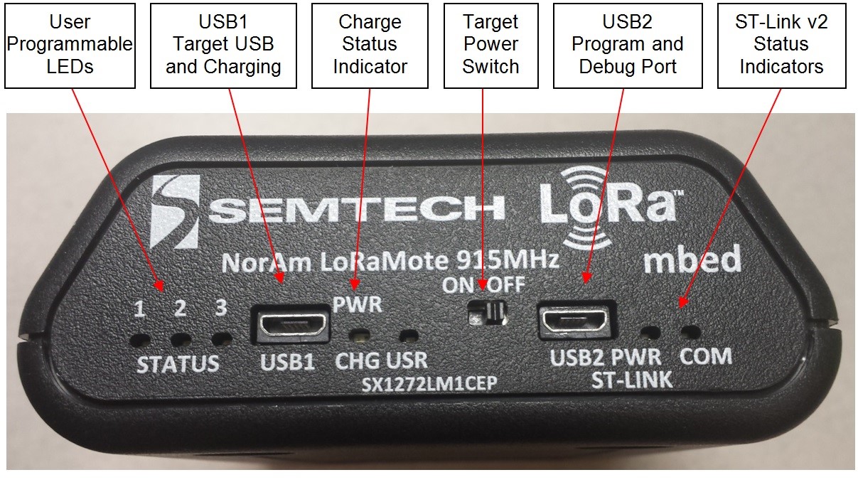
When the device is turned on the USR LED will blink while it is joining the Senet Network. When LED state changes to solid green it has joined the network. Failure to join network will be the result of:
- No network coverage in that area
- App Key configuration is incorrect
Siting Mode
The device is in Siting test mode when positioned vertically with LEDs facing up. The Siting test consists of transmitting Senet GPS packets with acknowledgment requested at transmit power levels 14, 20, 30 in that order. For each power level the device will attempt 3 transmits at DR0, stopping if ack is received and moving on to next tx power. After first run through all powers at DR0 the test will stop if acknowledgements received at all power levels; otherwise, the test will proceed to alternate between 3 transmits at DR4 and 3 at DR0 for remaining unacknowledged tx powers until ack received.
Siting LED Profile
- USR
- Blink fast while joining
- Solid when joined and GPS lock
- Blink slow when not GPS lock
- RED
- 30 dBm status indicator
- Blink on transmit
- Solid after downlink received
- YELLOW
- 20 dBm status indicator
- Blink on transmit
- Solid after ack received
- GREEN
- 14 dBm status indicator
- Blink on transmit
- Solid after downlink received
Range Mode
The device is in this mode when not in the siting orientation.
This test consists of transmitting 8 packets at:
- DR3 Tx Power 14
- DR0 Tx Power 14
- DR4 Tx Power 20
- DR3 Tx Power 20
- DR0 Tx Power 20
- DR4 Tx Power 26
- DR3 Tx Power 30
- DR0 Tx Power 30
After transmit cycle completes the next test will start in 560 seconds unless following:
- After 140 seconds if no ack received
- After 80 seconds if 30 meters travelled from last transmit location
Range LED Profile
- USR
- Blink fast while joining
- Solid when joined and GPS lock
- Blink slow when not GPS locked
- RED
- Transmit indicator
- Blink on transmit
- YELLOW
- Ack indicator
- Set at beginning of transmit cycle and cleared when ack received
- GREEN
- V3 Mote
- Test indicator
- Solid while test transmit cycle in progress
- V2 Mote
- Not controllable by firmware
- V3 Mote
Switching Mode
Set mote orientation to desired mode. After a few seconds the new orientation will be detected and the device will indicate it is switching mode by blinking the red, yellow and green LEDs simultaneously for a couple seconds before switching to the new mode.