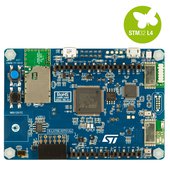
Mbed OS and Pelion Device Management example over WIFI for DISCO_L475VG_IOT01 board
Dependencies: X_NUCLEO_COMMON ST_INTERFACES
DEPRECATED
This example application is not maintained and not recommended. It uses an old version of Mbed OS, Pelion DM and Arm toolchain. It doesn't work with Mbed Studio.
Please use: https://os.mbed.com/teams/mbed-os-examples/code/mbed-os-example-pelion/
This example is known to work on the following platforms:
- DISCO_L475E_IOT01A over WiFI and using onboard QSPI flash.

Follow the Quick-Start instructions: https://cloud.mbed.com/quick-start
Example functionality
This example showcases the following device functionality:
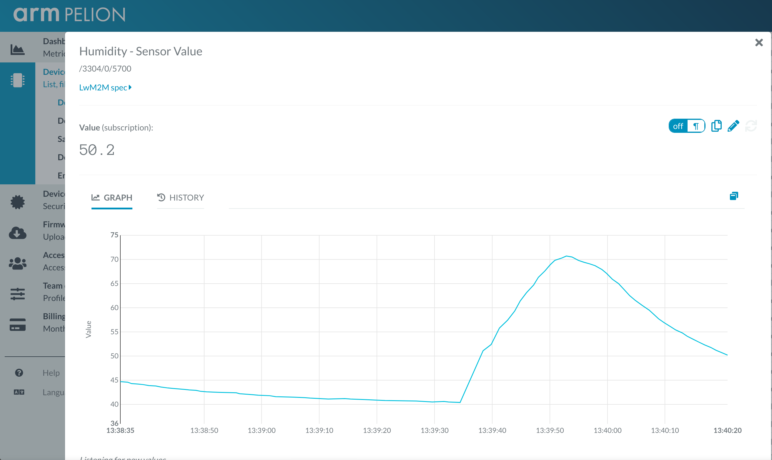
- Read onboard temperature and humidity sensors, and report them as Pelion LWM2M resources (see image below).
- On user button click, increment Pelion LWM2M button resource.
- Allow the user to change the state of the board LED from Pelion LWM2M led_state resource and PUT request.
- Uses all onboard sensors and reports them as Pelion LWM2M resources.

Use this example with Mbed CLI
1. Import the application into your desktop:
mbed import https://os.mbed.com/teams/ST/code/pelion-example-disco-iot01

cd pelion-example-disco-iot01
2. Install the CLOUD_SDK_API_KEY
mbed config -G CLOUD_SDK_API_KEY <PELION_DM_API_KEY>
For instructions on how to generate your API key, please see the documentation.
3. Initialize firmware credentials (done once per repository). You can use the following command:
mbed dm init -d "<your company name in Pelion DM>" --model-name "<product model identifier>" -q --force
If above command do not work for your Mbed CLI, please consider upgrading Mbed CLI to version 1.8.x or above.
4. Compile and program:
mbed compile -t <toolchain> -m DISCO_L475VG_IOT01A
(supported toolchains : GCC_ARM / ARM / IAR)
5. You can connect on a virtual terminal/COM port to the platform using:
mbed sterm -b 115200
This should give you an output similar to:
[BOOT] Mbed Bootloader
[BOOT] ARM: 00000000000000000000
[BOOT] OEM: 00000000000000000000
[BOOT] Layout: 0 80096F4
[BOOT] Active firmware integrity check:
[BOOT] SHA256: 0660E360D432225D5251461998FD8617B017098C5F1F90D5FB607BF8C27ED530
[BOOT] Version: 1553615309
[BOOT] Slot 0 is empty
[BOOT] Active firmware up-to-date
[BOOT] Application's start address: 0x8010400
[BOOT] Application's jump address: 0x8011041
[BOOT] Application's stack address: 0x20018000
[BOOT] Forwarding to application...

Starting Simple Pelion Device Management Client example
You can hold the user button during boot to format the storage and change the device identity.

Sensors configuration:
Invalid new address!
HTS221  humidity & temperature    = 0xBC
LPS22HB pressure & temperature    = 0xB1
LIS3MDL magnetometer              = 0x3D
LSM6DSL accelerometer & gyroscope = 0x6A

Connecting to the network using Wifi...
Connected to the network successfully. IP address: 192.168.1.3
Initializing Pelion Device Management Client...
Initialized Pelion Client. Registering...
Registered to Pelion Device Management. Endpoint Name: 0169********************001002d5

ADC temp:     23.0037 C,  vref:      0.3661 V
HTS221 temp:   28.700 C,  humidity:   31.90 %
LPS22HB temp:  29.600 C,  pressure: 1032.01 mbar
LIS3MDL mag:    0.217 x,  -0.284 y,  -0.053 z [gauss]
LSM6DSL acc:    0.005 x,  -0.014 y,   1.029 z [g]
LSM6DSL gyro:   0.910 x,  -0.910 y,   1.120 z [dps]
VL53L0X dist:    1855 mm
sensors/VL53L0X/STMPE1600/Stmpe1600.h
- Committer:
- chris
- Date:
- 2020-03-13
- Revision:
- 36:aaf44d2a6c33
- Parent:
- 18:a15bfe7aaebd
File content as of revision 36:aaf44d2a6c33:
/**
******************************************************************************
* @file Stmpe1600.h
* @author AST / EST
* @version V0.0.1
* @date 14-April-2015
* @brief Header file for component stmpe1600
******************************************************************************
* @attention
*
* <h2><center>© COPYRIGHT(c) 2015 STMicroelectronics</center></h2>
*
* Redistribution and use in source and binary forms, with or without modification,
* are permitted provided that the following conditions are met:
* 1. Redistributions of source code must retain the above copyright notice,
* this list of conditions and the following disclaimer.
* 2. Redistributions in binary form must reproduce the above copyright notice,
* this list of conditions and the following disclaimer in the documentation
* and/or other materials provided with the distribution.
* 3. Neither the name of STMicroelectronics nor the names of its contributors
* may be used to endorse or promote products derived from this software
* without specific prior written permission.
*
* THIS SOFTWARE IS PROVIDED BY THE COPYRIGHT HOLDERS AND CONTRIBUTORS "AS IS"
* AND ANY EXPRESS OR IMPLIED WARRANTIES, INCLUDING, BUT NOT LIMITED TO, THE
* IMPLIED WARRANTIES OF MERCHANTABILITY AND FITNESS FOR A PARTICULAR PURPOSE ARE
* DISCLAIMED. IN NO EVENT SHALL THE COPYRIGHT HOLDER OR CONTRIBUTORS BE LIABLE
* FOR ANY DIRECT, INDIRECT, INCIDENTAL, SPECIAL, EXEMPLARY, OR CONSEQUENTIAL
* DAMAGES (INCLUDING, BUT NOT LIMITED TO, PROCUREMENT OF SUBSTITUTE GOODS OR
* SERVICES; LOSS OF USE, DATA, OR PROFITS; OR BUSINESS INTERRUPTION) HOWEVER
* CAUSED AND ON ANY THEORY OF LIABILITY, WHETHER IN CONTRACT, STRICT LIABILITY,
* OR TORT (INCLUDING NEGLIGENCE OR OTHERWISE) ARISING IN ANY WAY OUT OF THE USE
* OF THIS SOFTWARE, EVEN IF ADVISED OF THE POSSIBILITY OF SUCH DAMAGE.
*
******************************************************************************
*/
#ifndef __STMPE1600_CLASS
#define __STMPE1600_CLASS
/* Includes ------------------------------------------------------------------*/
#include "DevI2C.h"
#define STMPE1600_DEF_DEVICE_ADDRESS (uint8_t)0x42*2
#define STMPE1600_DEF_DIGIOUT_LVL 1
/** STMPE1600 registr map **/
#define CHIP_ID_0_7 (uint8_t)0x00
#define CHIP_ID_8_15 (uint8_t)0x01
#define VERSION_ID (uint8_t)0x02
#define SYS_CTRL (uint8_t)0x03
#define IEGPIOR_0_7 (uint8_t)0x08
#define IEGPIOR_8_15 (uint8_t)0x09
#define ISGPIOR_0_7 (uint8_t)0x0A
#define ISGPIOR_8_15 (uint8_t)0x0B
#define GPMR_0_7 (uint8_t)0x10
#define GPMR_8_15 (uint8_t)0x11
#define GPSR_0_7 (uint8_t)0x12
#define GPSR_8_15 (uint8_t)0x13
#define GPDR_0_7 (uint8_t)0x14
#define GPDR_8_15 (uint8_t)0x15
#define GPIR_0_7 (uint8_t)0x16
#define GPIR_8_15 (uint8_t)0x17
#define SOFT_RESET (uint8_t)0x80
typedef enum {
// GPIO Expander pin names
GPIO_0 = 0,
GPIO_1,
GPIO_2,
GPIO_3,
GPIO_4,
GPIO_5,
GPIO_6,
GPIO_7,
GPIO_8,
GPIO_9,
GPIO_10,
GPIO_11,
GPIO_12,
GPIO_13,
GPIO_14,
GPIO_15,
NOT_CON
} ExpGpioPinName;
typedef enum {
INPUT = 0,
OUTPUT,
NOT_CONNECTED
} ExpGpioPinDirection;
/* Classes -------------------------------------------------------------------*/
/** Class representing a single stmpe1600 GPIO expander output pin
*/
class Stmpe1600DigiOut
{
public:
/** Constructor
* @param[in] &i2c device I2C to be used for communication
* @param[in] outpinname the desired out pin name to be created
* @param[in] DevAddr the stmpe1600 I2C device address (deft STMPE1600_DEF_DEVICE_ADDRESS)
* @param[in] lvl the default ot pin level
*/
Stmpe1600DigiOut(DevI2C *i2c, ExpGpioPinName out_pin_name, uint8_t dev_addr = STMPE1600_DEF_DEVICE_ADDRESS,
bool lvl = STMPE1600_DEF_DIGIOUT_LVL) : _dev_i2c(i2c), exp_dev_addr(dev_addr), exp_pin_name(out_pin_name)
{
uint8_t data[2];
if (exp_pin_name == NOT_CON) {
return;
}
/* set the exp_pin_name as output */
_dev_i2c->i2c_read(data, exp_dev_addr, GPDR_0_7, 1);
_dev_i2c->i2c_read(&data[1], exp_dev_addr, GPDR_8_15, 1);
* (uint16_t *) data = * (uint16_t *) data | (1 << (uint16_t) exp_pin_name); // set gpio as out
_dev_i2c->i2c_write(data, exp_dev_addr, GPDR_0_7, 1);
_dev_i2c->i2c_write(&data[1], exp_dev_addr, GPDR_8_15, 1);
write(lvl);
}
/**
* @brief Write on the out pin
* @param[in] lvl level to write
* @return 0 on Success
*/
void write(int lvl)
{
uint8_t data[2];
if (exp_pin_name == NOT_CON) {
return;
}
/* set the exp_pin_name state to lvl */
_dev_i2c->i2c_read(data, exp_dev_addr, GPSR_0_7, 2);
* (uint16_t *) data = * (uint16_t *) data & (uint16_t)(~(1 << (uint16_t) exp_pin_name)); // set pin mask
if (lvl) {
* (uint16_t *) data = * (uint16_t *) data | (uint16_t)(1 << (uint16_t) exp_pin_name);
}
_dev_i2c->i2c_write(data, exp_dev_addr, GPSR_0_7, 2);
}
/**
* @brief Overload assignement operator
*/
Stmpe1600DigiOut &operator= (int lvl)
{
write(lvl);
return *this;
}
private:
DevI2C *_dev_i2c;
uint8_t exp_dev_addr;
ExpGpioPinName exp_pin_name;
};
/* Classes -------------------------------------------------------------------*/
/** Class representing a single stmpe1600 GPIO expander input pin
*/
class Stmpe1600DigiIn
{
public:
/** Constructor
* @param[in] &i2c device I2C to be used for communication
* @param[in] inpinname the desired input pin name to be created
* @param[in] DevAddr the stmpe1600 I2C device addres (deft STMPE1600_DEF_DEVICE_ADDRESS)
*/
Stmpe1600DigiIn(DevI2C *i2c, ExpGpioPinName in_pin_name,
uint8_t dev_addr = STMPE1600_DEF_DEVICE_ADDRESS) : _dev_i2c(i2c), exp_dev_addr(dev_addr),
exp_pin_name(in_pin_name)
{
uint8_t data[2];
if (exp_pin_name == NOT_CON) {
return;
}
/* set the exp_pin_name as input pin direction */
_dev_i2c->i2c_read(data, exp_dev_addr, GPDR_0_7, 2);
* (uint16_t *) data = * (uint16_t *) data & (uint16_t)(~(1 << (uint16_t) exp_pin_name)); // set gpio as in
_dev_i2c->i2c_write(data, exp_dev_addr, GPDR_0_7, 2);
}
/**
* @brief Read the input pin
* @return The pin logical state 0 or 1
*/
bool read()
{
uint8_t data[2];
if (exp_pin_name == NOT_CON) {
return false;
}
/* read the exp_pin_name */
_dev_i2c->i2c_read(data, exp_dev_addr, GPMR_0_7, 2);
* (uint16_t *) data = * (uint16_t *) data & (uint16_t)(1 << (uint16_t) exp_pin_name); // mask the in gpio
if (data[0] || data[1]) {
return true;
}
return false;
}
operator int()
{
return read();
}
private:
DevI2C *_dev_i2c;
uint8_t exp_dev_addr;
ExpGpioPinName exp_pin_name;
};
/* Classes -------------------------------------------------------------------*/
/** Class representing a whole stmpe1600 component (16 gpio)
*/
class Stmpe1600
{
public:
/** Constructor
* @param[in] &i2c device I2C to be used for communication
* @param[in] DevAddr the stmpe1600 I2C device addres (deft STMPE1600_DEF_DEVICE_ADDRESS)
*/
Stmpe1600(DevI2C *i2c, uint8_t dev_addr = STMPE1600_DEF_DEVICE_ADDRESS) : _dev_i2c(i2c)
{
exp_dev_addr = dev_addr;
write_sys_ctrl(SOFT_RESET);
gpdr0_15 = (uint16_t) 0; // gpio dir all IN
write_16bit_reg(GPDR_0_7, &gpdr0_15);
gpsr0_15 = (uint16_t) 0x0ffff; // gpio status all 1
write_16bit_reg(GPSR_0_7, &gpsr0_15);
}
/**
* @brief Write the SYS_CTRL register
* @param[in] Data to be written (bit fields)
*/
void write_sys_ctrl(uint8_t data) // data = SOFT_RESET reset the device
{
_dev_i2c->i2c_write(&data, exp_dev_addr, SYS_CTRL, 1);
}
/**
* @brief Set the out pin
* @param[in] The pin name
* @return 0 on Success
*/
bool set_gpio(ExpGpioPinName pin_name)
{
if (pin_name == NOT_CON) {
return true;
}
gpsr0_15 = gpsr0_15 | ((uint16_t) 0x0001 << pin_name);
write_16bit_reg(GPSR_0_7, &gpsr0_15);
return false;
}
/**
* @brief Clear the out pin
* @param[in] The pin name
* @return 0 on Success
*/
bool clear_gpio(ExpGpioPinName pin_name)
{
if (pin_name == NOT_CON) {
return true;
}
gpsr0_15 = gpsr0_15 & (~((uint16_t) 0x0001 << pin_name));
write_16bit_reg(GPSR_0_7, &gpsr0_15);
return false;
}
/**
* @brief Read the input pin
* @param[in] The pin name
* @return The logical pin level
*/
bool read_gpio(ExpGpioPinName pin_name)
{
uint16_t gpmr0_15;
if (pin_name == NOT_CON) {
return true;
}
read_16bit_reg(GPMR_0_7, &gpmr0_15);
gpmr0_15 = gpmr0_15 & ((uint16_t) 0x0001 << pin_name);
if (gpmr0_15) {
return true;
}
return false;
}
/**
* @brief Set the pin direction
* @param[in] The pin name
* @param[in] The pin direction
* @return 0 on success
*/
bool set_gpio_dir(ExpGpioPinName pin_name, ExpGpioPinDirection pin_dir)
{
if (pin_name == NOT_CON || pin_dir == NOT_CONNECTED) {
return true;
}
gpdr0_15 = gpdr0_15 & (~((uint16_t) 0x0001 << pin_name)); // clear the Pin
gpdr0_15 = gpdr0_15 | ((uint16_t) pin_dir << pin_name);
write_16bit_reg(GPDR_0_7, &gpdr0_15);
return false;
}
/**
* @brief Read a 16 bits register
* @param[in] The register address
* @param[in] The pointer to the read data
*/
void read_16bit_reg(uint8_t reg16_addr, uint16_t *reg16_data)
{
_dev_i2c->i2c_read((uint8_t *) reg16_data, exp_dev_addr, reg16_addr, 2);
}
/**
* @brief Write a 16 bits register
* @param[in] The register address
* @param[in] The pointer to the data to be written
*/
void write_16bit_reg(uint8_t reg16_addr, uint16_t *reg16_data)
{
_dev_i2c->i2c_write((uint8_t *) reg16_data, exp_dev_addr, reg16_addr, 2);
}
private:
DevI2C *_dev_i2c;
uint16_t gpdr0_15; // local copy of bit direction reg
uint16_t gpsr0_15; // local copy of bit status reg
uint8_t exp_dev_addr; // expander device i2c addr
};
#endif // __STMPE1600_CLASS

