Example application for X-NUCLEO-IHM07M1 board connected to a 3-phase brushless motor with Hall sensors.
Dependencies: BLDCmotorDriver RateLimiter mbed
Fork of HelloWorld_IHM07M1 by
Getting Started with X-NUCLEO-IHM07M1
This example demonstrates how to use the X-NUCLEO-IHM07M1 component with one of the STM32 Nucleo-64 platforms and a three-phase brushless DC (BLDC) motor with Hall sensors.
HW Prerequisites
- X-NUCLEO-IHM07M1
- STM32 Nucleo-64 board
- external DC power supply
- low voltage three-phase BLDC motor with Hall sensors
X-NUCLEO-IHM07M1 Jumpers Configuration

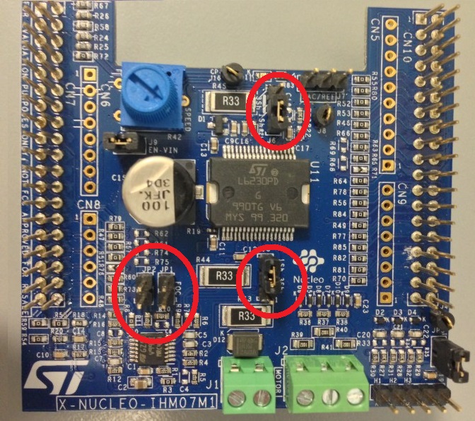
Configure the jumpers of your X-NUCLEO-IHM07M1 board as shown below:
- JP1 open
- JP2 open
- JP3 closed
- J9 closed
- J5 closed on 2-3 (single shunt)
- J6 closed on 2-3 (single shunt)
- J7 open
For more details please refer to the X-NUCLEO-IHM07M1 user manual.
BLDCmotorDriver Library
This example is based on the BLDCmotorDriver motor control library by the TVZ Mechatronics Team, University of Applied Sciences Zagreb, Professional Study in Mechatronics. The BLDCmotorDriver library is a simple implementation of the six-step algorithm and needs Hall sensors to estimate the correct timing for commutation. If you want to use sensor-less BLDC motors with X-NUCLEO-IHM07M1 or if you want an optimized implementation, you must use a different software package like X-CUBE-SPN7, based on STM32Cube.
The HelloWorld_IHM07M1 application has been tested with the Nanotec DF45M024053-A2 motor, a 24V three-phase brushless motor with Hall sensors. This example implements a temperature check to prevent overheating.
If you use a different motor, please be advised that you may need to tweak the configuration parameters for the BLDCmotorDriver library.
Connecting the Motor

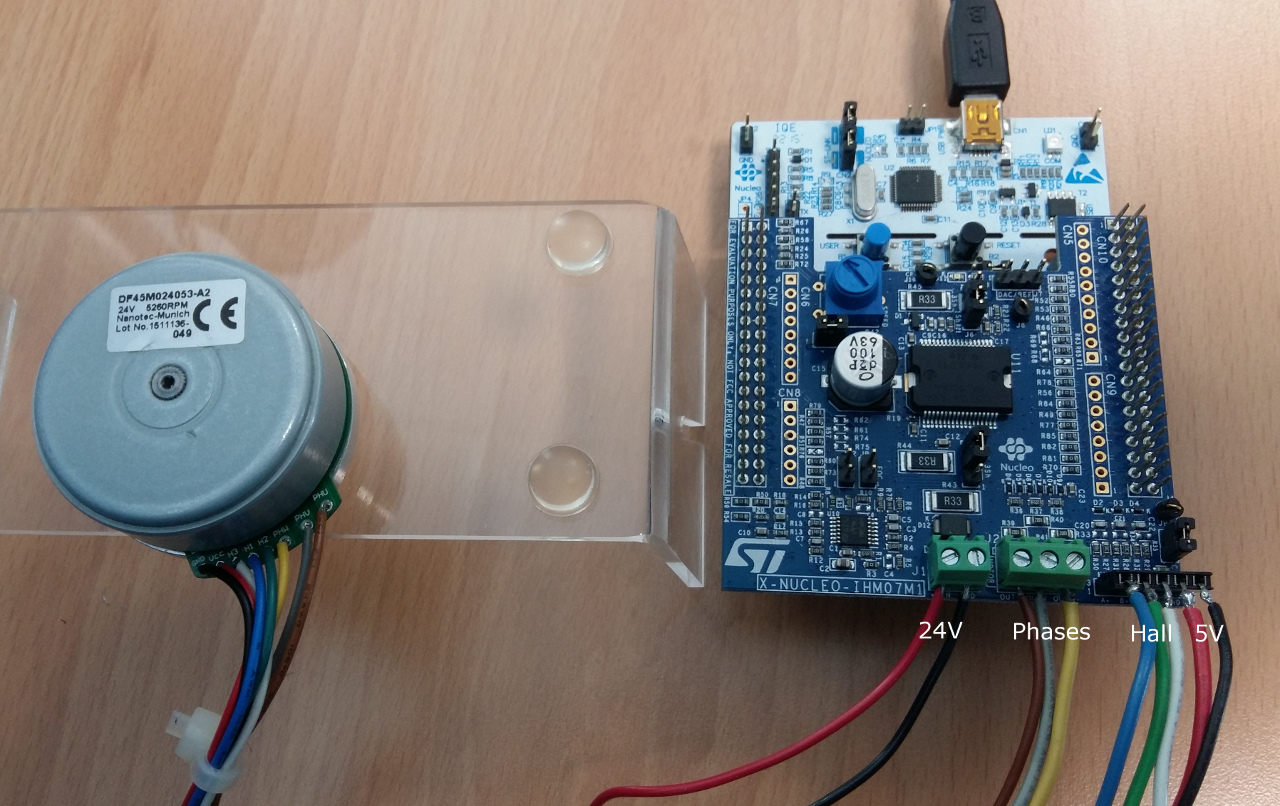
In the picture above you can see an example setup with the Nanotec DF45M024053-A2 motor and a 24V power supply.
If you use the same motor, please connect the brown, grey and yellow phases to the OUT1, OUT2 and OUT3 connectors of the X-NUCLEO-IHM07M1 board respectively. Then connect the blue, green, white, red and black wires for the Hall sensors to the A+/H1, B+/H2, Z+/H3, 5V, GND connectors as shown in the picture.
If your motor is different, you must pay attention to connect the motor phases and Hall sensors pins in the correct order otherwise the motor won't spin.
Spinning the Motor
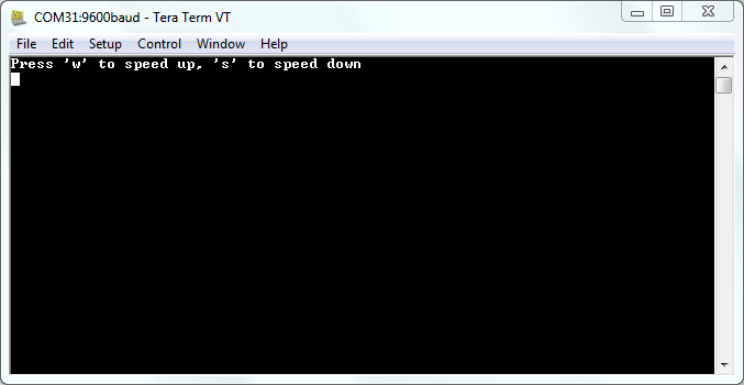
Open a terminal window (baudrate 9600, 8N1) to display the user interface of the HelloWorld_IHM07M1 application.
Press the 'w' character to start spinning the motor and speed it up; press the 's' character to slow it down and turn it off.

Note
You need a terminal emulator installed on your PC to perform serial communications with your STM32 Nucleo platform. If you do not have it, please download and install one of the following terminal emulation programs:
X_NUCLEO_IHM07M1/SPN7Driver.cpp
- Committer:
- avilei
- Date:
- 2016-10-20
- Revision:
- 12:33614e1dc638
- Parent:
- 11:0120619cdfb7
File content as of revision 12:33614e1dc638:
/* mbed Microcontroller Library
* Copyright (c) 2006-2016 ARM Limited
*
* Licensed under the Apache License, Version 2.0 (the "License");
* you may not use this file except in compliance with the License.
* You may obtain a copy of the License at
*
* http://www.apache.org/licenses/LICENSE-2.0
*
* Unless required by applicable law or agreed to in writing, software
* distributed under the License is distributed on an "AS IS" BASIS,
* WITHOUT WARRANTIES OR CONDITIONS OF ANY KIND, either express or implied.
* See the License for the specific language governing permissions and
* limitations under the License.
*/
/**
******************************************************************************
* @file SPN7Driver.cpp
* @author STMicroelectronics
* @brief Implementation of SPN7Driver class
******************************************************************************
* @copy
*
* THE PRESENT FIRMWARE WHICH IS FOR GUIDANCE ONLY AIMS AT PROVIDING CUSTOMERS
* WITH CODING INFORMATION REGARDING THEIR PRODUCTS IN ORDER FOR THEM TO SAVE
* TIME. AS A RESULT, STMICROELECTRONICS SHALL NOT BE HELD LIABLE FOR ANY
* DIRECT, INDIRECT OR CONSEQUENTIAL DAMAGES WITH RESPECT TO ANY CLAIMS ARISING
* FROM THE CONTENT OF SUCH FIRMWARE AND/OR THE USE MADE BY CUSTOMERS OF THE
* CODING INFORMATION CONTAINED HEREIN IN CONNECTION WITH THEIR PRODUCTS.
*
* <h2><center>© COPYRIGHT 2016 STMicroelectronics</center></h2>
*/
// This example is based on the BLDCmotorDriver motor control library
// by the TVZ Mechatronics Team, University of Applied Sciences Zagreb,
// Professional Study in Mechatronics:
// https://developer.mbed.org/teams/TVZ-Mechatronics-Team/code/BLDCmotorDriver/
#include "mbed.h"
#include "SPN7Driver.h"
typedef enum {
ST_BLDC_LOW = 0,
ST_BLDC_HIGH,
ST_BLDC_OFF
} st_bldc_status_t;
/**************************************************************************/
/**
@brief Constructor
* @param pIN1 Logic input pin IN1 of L6230 chip
* @param pIN2 Logic input pin IN2 of L6230 chip
* @param pIN3 Logic input pin IN3 of L6230 chip
* @param pEN1 Enable channel pin EN1 of L6230 chip
* @param pEN2 Enable channel pin EN2 of L6230 chip
* @param pEN3 Enable channel pin EN3 of L6230 chip
* @param pH1 Hall sensor pin for phase #1 (A) of X-NUCLEO-IHM07M1
* @param pH2 Hall sensor pin for phase #2 (B) of X-NUCLEO-IHM07M1
* @param pH3 Hall sensor pin for phase #3 (Z) of X-NUCLEO-IHM07M1
* @param pFault Fault LED pin of X-NUCLEO-IHM07M1
*/
/**************************************************************************/
SPN7Driver::SPN7Driver(PinName pIN1, PinName pIN2, PinName pIN3,
PinName pEN1, PinName pEN2, PinName pEN3,
PinName pH1, PinName pH2, PinName pH3,
PinName pFault) :
BLDCmotorDriver(pIN1, pIN2, pIN3,
pEN1, pEN2, pEN3,
pH1, pH2, pH3,
pFault)
{
// The BLDCmotorDriver class was implemented for half-bridge drivers
// so the pin names may be misleading when referring to the L6230 chip.
// Get pointers to each input pin and call them IN[x] (logic input)
// to be consistent with the terminology used in the L6230 documentation.
PwmOut* IN[3] = {&GH_A, &GH_B, &GH_C};
// Set the switching period of the INx logic input pins (PWM driven)
for (int i = 0; i < 3; i++) {
IN[i]->period(switchingPeriod);
}
// Set the step commutation function (triggered by the Hall sensors)
H1.rise(this, &SPN7Driver::commutation);
H2.rise(this, &SPN7Driver::commutation);
H3.rise(this, &SPN7Driver::commutation);
H1.fall(this, &SPN7Driver::commutation);
H2.fall(this, &SPN7Driver::commutation);
H3.fall(this, &SPN7Driver::commutation);
}
/**************************************************************************/
/**
@brief Set duty cycle for motor control
* @param dc duty cycle value (>0 clockwise; <0 anti-clockwise)
*/
/**************************************************************************/
void SPN7Driver::setDutyCycle(float dc) {
if (dc >= -1 && dc <= 1) {
ticker.attach(this, &SPN7Driver::commutation, sampleTime);
tempDutyCycle = dc;
} else {
coast();
}
}
// six-step phase commutation
void SPN7Driver::commutation()
{
// The BLDCmotorDriver class was implemented for half-bridge drivers
// so the pin names may be misleading when referring to the L6230 chip.
// Get pointers to each input pin and call them IN[x] (logic input)
// to be consistent with the terminology used in the L6230 documentation.
PwmOut* IN[3] = {&GH_A, &GH_B, &GH_C};
// Get pointers to each enable pin and call them ENx (enable channel)
// to be consistent with the terminology used in the L6230 documentation.
DigitalOut* EN[3] = {&GL_A, &GL_B, &GL_C};
st_bldc_status_t tab[6][3] = {
{ST_BLDC_OFF, ST_BLDC_LOW, ST_BLDC_HIGH},
{ST_BLDC_HIGH, ST_BLDC_LOW, ST_BLDC_OFF},
{ST_BLDC_HIGH, ST_BLDC_OFF, ST_BLDC_LOW},
{ST_BLDC_OFF, ST_BLDC_HIGH, ST_BLDC_LOW},
{ST_BLDC_LOW, ST_BLDC_HIGH, ST_BLDC_OFF},
{ST_BLDC_LOW, ST_BLDC_OFF, ST_BLDC_HIGH},
};
dutyCycle = rl.out(tempDutyCycle);
int sector = getSector();
if (dutyCycle == 0) {
// Stop the motor
coast();
return;
}
// Move to next sector (i.e. commute phase)
if (dutyCycle > 0 ) {
// Clockwise spinning
// The rows of the phase status table are offset by one when spinning
// clockwise so we need to increment the current sector by two steps
sector = (sector + 2) % 6;
} else {
// Anti-clockwise spinning
sector--;
if(sector < 0) sector = 5;
}
// Get the absolute value of the duty cycle for the PWM
float d = (dutyCycle > 0) ? dutyCycle : -dutyCycle;
// Update the logic inputs and the enable pins
for (int i = 0; i < 3; i++) {
*EN[i] = (tab[sector][i] == ST_BLDC_OFF) ? 0 : 1;
*IN[i] = (tab[sector][i] == ST_BLDC_HIGH) ? d : 0;
}
}

 X-NUCLEO-IHM07M1 Brushless DC Motor Driver