Important changes to repositories hosted on mbed.com
Mbed hosted mercurial repositories are deprecated and are due to be permanently deleted in July 2026.
To keep a copy of this software download the repository Zip archive or clone locally using Mercurial.
It is also possible to export all your personal repositories from the account settings page.
Configure
How to configure the project
These steps are necessary in order to compile the project for the first time.
Nucleo ST-LINK/V2 driver installation
Install the ST-LINK/V2 driver before connecting the SensorNode board to your PC the first time.
1. Download the latest ST-LINK/V2 driver
2. Extract the archive and run either dpinst_amd64.exe or dpinst_x86.exe depending on whether you are on a 64-bit machine or 32-bit machine. Follow the displayed instructions.
3. You should now have successfully installed the ST-LINK/V2 driver
Create a developer mbed account
This example sends data to the cloud named mbed Device Connector. It is required to register at mbed Device Connector website in order to use the demo.

Configure the project before to compile it
1. From the root of the project open *mbed_app.json* file and modify the following line:
- change "spirit1.mac-address": "{0x7, 0x6, 0x5, 0x4, 0x3, MONTH, DAY, YEAR}" substituting MONTH, DAY, YEAR with hex numbers. For example your birth date.
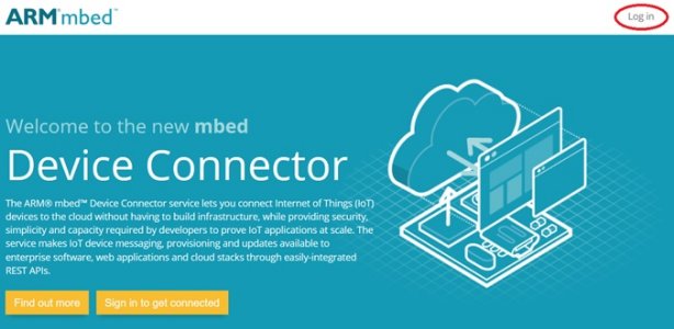
2. Go to mbed device connector webpage and login into it.
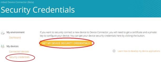
3. Go to the page Security Credentials and click on Get my device security credentials:

4. Copy the text shown on grey background.
5. In the root directory of the project open security.h file and paste substituting all text.
6. Now you are ready to compile the project.
Border Router
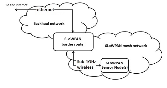
This client needs a Border Router board. Border router is a network gateway between a wireless 6LoWPAN mesh network (with nodes like the Sensor Node) and a backhaul network. It controls and relays traffic between the two networks. In this demo, a 6LoWPAN border router is connected to another router in the backhaul network over Ethernet which in turn forwards traffic to/from the internet. We have used the NUCLEO_F429ZI board with the SPIRIT module X-NUCLEO-IDS01A4.

Here the links to the boards:
- ST-Nucleo-F429ZI webpage
- x-nucleo-ids01a4 webpage
You have to modify the boards in order to use them in this demo:
- On the X-NUCLEO-IDS01A4:
- Unmount resistor R4
- Mount resistor R7
- On the NUCLEO_F429ZI:
- Open solder bridge SB121
- Close solder bridge SB122
If you don't want to build the firmware of the border router you can download it here
If you want to build it by yourself please visit the github page of nanostack-border-router
Jumpers settings
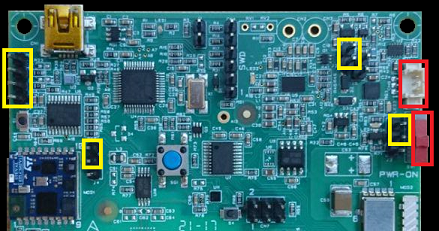
Please close with jumpers the following pins marked as yellow in order to power supply the board via micro-usb cable.

In the red rectangles, with this configuration is not important if you have connected the battery and if the switch is closed or open.
Now you are ready to run the example. Please read this page