Important changes to forums and questions
All forums and questions are now archived. To start a new conversation or read the latest updates go to forums.mbed.com.
9 years, 8 months ago.
How to choose the Crystal and loading capacitor for customized PCB?
Hello guys,
I need your help. I designed my own PCB and use mbed to program. However, it seems that my external crystal won't boot up the STM32F411. A detailed description of the problem can be found at another post of mine:
https://developer.mbed.org/questions/61589/Program-hangs-at-SetSysClock-on-a-custom/
The detailed info for crystal and loading capacitor I chose is here:
- Crystal: 8MHz ±30ppm Crystal 20pF 80 Ohm -10°C ~ 70°C Through Hole HC49/US http://www.digikey.com/product-search/en/crystals-and-oscillators/crystals/852333?k=X1094-ND
- Loading Capacitor: 20pF, ±5%, 50V, http://www.digikey.com/product-search/en?keywords=490-1410-1-ND
Is there anything wrong with my choice? Thank you so much for the help and I really appreciate it.
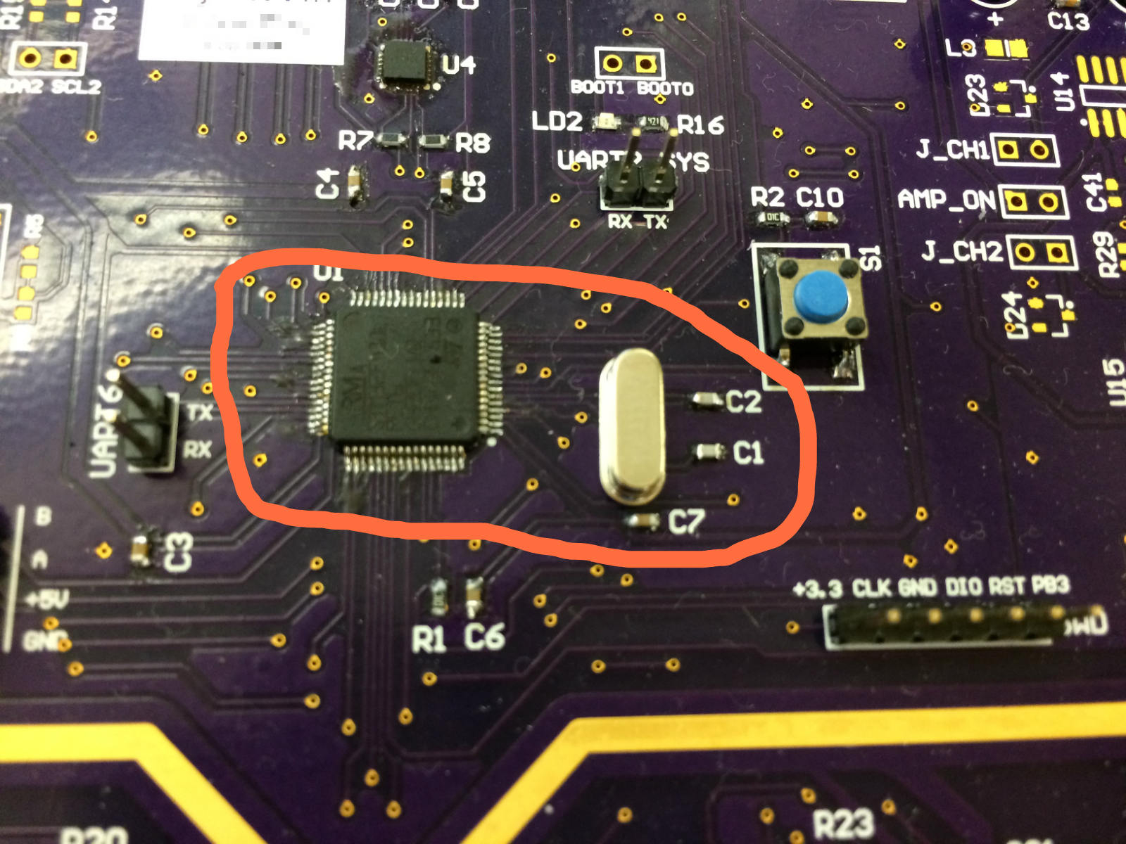
[Edit update]: I uploaded the schematic for the microcontroller and the actual picture of the PCB. Can someone figure out what the problem is?


Question relating to:

4 Answers
9 years, 7 months ago.
I'd try reducing the capacitor values by around 10pF and see if that helps. Also keep in mind that looking at this sort of thing with an oscilloscope can be misleading, the scope probe will add 15pF which can change how things are working.
Also your PCB layout isn't great, it's a little late to fix that but keep it in mind for the next board. Ideally you should connect the crystal to the CPU with as short a trace as possible and then place the capacitors along those traces without any stubs. Putting them on the end of a stub that is far longer than it needs to be and on the opposite side of the crystal isn't a good idea. It should still work but the capacitor values become a lot more critical.
To be honest you've got far bigger problems than that with your layout, C3-C7 are far too far away from the CPU. They should be right on the power and ground pins with a thick a traces as possible connecting them to the power supply and the chip. With the layout you've got the impedance on your CPU power is going to be far higher than it should, you could well find that at high speed it will simply crash at random.
Looking closer I can't even see any connection at all from C4 and C5 to the CPU and I'm not sure how the power gets to C6 & C7 unless it's coming in from a trace that runs under the CPU. C3 looks to be connected correctly, power goes to the cap and then from there to the CPU. But the trace to the CPU is far too long and thin. To be honest I'm impressed that the CPU runs at all.
posted by 20 Apr 2016Hi thanks for the great comments. I think your answer should be a very good explanation for my problem. Also your comments on C3-C7 are absolutely right and I'll keep in mind for the next board. Also do you think if it is necessary to add R_ext?
posted by 21 Apr 2016By R_ext you mean an extra resistor on the crystal lines? I can't see provision for one on the PCB so you'd have to make a change to try that. I doubt it would help much. If changing the cap values doesn't fix it then you could try cutting the tracks going to C1 & C2 as close to the crystal pins as possible a use a knife to scratch off the solder resist on the tracks from the crystal to the CPU and place the capacitors there. Getting a good ground connection in that situation can be hard, it's tricky to get enough heat into the ground sometimes due to the large amount of copper.
You are sure that the problem is the crystal and not the CPU crashing when it tries to run at a higher speed due to the power connections?
posted by 21 Apr 20169 years, 7 months ago.
IMO Fundamental mode crystals should be fairly straightforward and these days that should cover up to about 25MHz. Things I'd try in order of difficulty:
- Checking the seating of the crystal, can-to-pad short circuits are possible with some crystal footprints
- Remove the crystal, drive osc_in with an external clock and measure osc_out. If there isn't a signal on osc_out it might not be configured as an oscillator
- Get hold of a 74HCU04 hex unbuffered inverter and try to make the crystal oscillate with that. If it won't oscillate with the HCU04 the crystal might be faulty.
9 years, 8 months ago.
Have you fitted the crystal option to the Nucleo board and does this run correctly?
If it does, then the mbed start up process is working so the problem may be with your hardware.
Try extending the HSE time out value form 200ms to 500ms in line 104, see here for the file to change:
If you have not already, you will need to replace your Mbed library folder with the MBED-DEV to make the changes.
9 years, 8 months ago.
Offical refence document is in here.
https://docs.google.com/viewer?url=http%3A%2F%2Fwww.st.com%2Fweb%2Fen%2Fresource%2Ftechnical%2Fdocument%2Fapplication_note%2FCD00221665.pdf%23search%3D%27AN2867%27
Thank you. I just uploaded the schematic and actual PCB picture, could you check if there is anything wrong with them? Thanks!
posted by 19 Apr 2016Please also refer doc here.
DocID026289 Rev 4 (February 2015)
https://docs.google.com/viewer?url=http%3A%2F%2Fwww2.st.com%2Fresource%2Fen%2Fdatasheet%2Fstm32f411re.pdf
In page 83 & 84, there are small explanation.
1) Capacitor's rage 5pF to 25pF (Typ.)
2) C1 & C2 are usually same value
3) PCB & F411 pin capacitance must be included (10pF <- rough estimation)