DISCO-L072CZ-LRWAN1
The B-L072Z-LRWAN1 LoRa®Discovery kit is a development tool to learn and develop solutions based on LoRa®and FSK/OOK technologies.
Overview
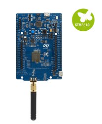
The B-L072Z-LRWAN1 LoRa®Discovery kit is a development tool to learn and develop solutions based on LoRa®and FSK/OOK technologies. This Discovery kit features an all-in-one open module CMWX1ZZABZ-091 (by Murata). The module is powered by an STM32L072CZ and an SX1276 transceiver. The transceiver features the LoRa®long-range modem, providing ultra-long-range spread spectrum communication and high interference immunity, minimizing current consumption. Since CMWX1ZZABZ-091 is an open module, user has access to all STM32L072 peripherals such as ADC, 16-bit timer, LP-UART, I2C, SPI and USB 2.0 FS (supporting BCD and LPM).
The B-L072Z-LRWAN1 Discovery kit includes an ST-LINK/V2-1 embedded debug tool interface, LEDs, push-buttons, antenna, Arduino™Uno V3 connectors and USB OTG connector in Micro-B format.
Microcontroller features
- CMWX1ZZABZ-091 LoRa® module with STM32L072CZ
- ARM® 32-bit Cortex®-M0+ CPU
- 32 MHz max CPU frequency
- VDD from 1.65 V to 3.6 V
- 192 KB Flash
- 20 KB SRAM
- GPIO (40) with external interrupt capability
- General-purpose Timer (4)
- Basic Timer (2)
- Low Power Timer
- SPI (6)
- I2S
- I2C (3)
- USART (4)
- Low-power UART
- USB 2.0 full-speed
- 12-bit ADC with 13 channels
- 12-bit DAC (2) with 1 channel each
- Comparators (2)
- RTC
- Capacitive sensing channels (19)
- Random Generator (TRNG for HW entropy)
Board features
- Two types of extension resources
- Arduino Uno Revision 3 connectivity
- STMicroelectronics extension pin headers for full access to all STM32 I/Os
- On-board ST-LINK/V2-1 debugger/programmer with SWD connector
- Selection-mode switch to use the kit as a standalone ST-LINK/V2-1
- Flexible board power supply
- USB VBUS or external source (3.3 V, 5 V, 7 - 12 V)
- Power management access point
- User LED (LD1, LD2, LD3, LD4)
- Two push buttons: USER and RESET
- USB re-enumeration capability: three different interfaces supported on USB
- Virtual Com port
- Mass storage (USB Disk drive) for drag'n'drop programming
- Debug port
Board pinout
Pins Legend

You can find more details on the available pins and labels in the PeripheralPins.c and PinNames.h files.
These files can be found in:
- ARMmbed/mbed-os repository on GitHub (up-to-date version, used with mbed CLI commands)
- mbed-dev library in developer.mbed.org (source files of the mbed library used on mbed compiler IDE)
Arduino-compatible headers


Morpho headers


Supported shields
ST X-NUCLEO boards
Other Non-ST boards
See here.
Technical references
For more information, please refer to:
Known limitations
The following section describes known limitations of the platform. Note that general issues are tracked into the mbed repository available on GitHub.
- There is no AnalogIn on Arduino A1, A3, A4, A5 pins.
- There is no PWM on Arduino D3, D5, D6, D9 pins.
- In order to use Serial (TX and RX) on Arduino D0 and D1 pins, you have to remove SB28 and SB29 solder bridges. In this case you will lose the ST-Link connection.
- The C24 capacitor must be removed if the MCO clock configuration is selected (SB36 closed and USE_PLL_HSE_EXTC config enabled in targets.json file).
Tips and Tricks
Find more information in ST WIKI pages.

To compile a program for this board using Mbed CLI, use disco_l072cz_lrwan1 as the target name.
Board Partner
ST
A world leader in providing the semiconductor solutions that make a positive contribution to people’s lives, both today and in the future.
 Mbed Enabled
- Baseline
Mbed OS support
- Mbed OS 2
- Mbed OS 5.10
- Mbed OS 5.11
- Mbed OS 5.12
- Mbed OS 5.13
- Mbed OS 5.14
- Mbed OS 5.15
- Mbed OS 5.4
- Mbed OS 5.5
- Mbed OS 5.6
- Mbed OS 5.7
- Mbed OS 5.8
- Mbed OS 5.9
- Mbed OS 6.0
- Mbed OS 6.1
- Mbed OS 6.10
- Mbed OS 6.11
- Mbed OS 6.12
- Mbed OS 6.13
- Mbed OS 6.14
- Mbed OS 6.15
- Mbed OS 6.2
- Mbed OS 6.3
- Mbed OS 6.4
- Mbed OS 6.5
- Mbed OS 6.6
- Mbed OS 6.7
- Mbed OS 6.8
- Mbed OS 6.9
Example programs