DISCO-F429ZI
The STM32F429 Discovery kit (STM32F429I-DISC1) allows users to easily develop applications with the STM32F429 high-performance MCUs with ARM®Cortex®-M4 core.
Overview
Support of STM32F429I-DISCO and DISC1 boards
Two different board references are available: STM32F429I-DISCO and STM32F429I-DISC1.
The discovery board referenced STM32F429I-DISCO does not support the drag&drop and Virtual Comm Port features. If you are using this board version, you will have to use an external tool (for example the STM32 STLink utility) to program your code .bin file. There is no possibility to use either the printf in your code.
The board referenced STM32F429I-DISC1 does not have these limitations.
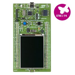
This discovery board offers everything required for users to get started quickly and develop applications easily. The full range of hardware features on the board helps to evaluate almost all peripherals and develop your own applications.
The STM32F429I-DISC1 board includes an ST-LINK/V2-B embedded debug tool, a 2.4" QVGA TFT LCD, an external 64-Mbit SDRAM, an ST MEMS gyroscope, a USB OTG micro-AB connector, LEDs and push-buttons.
Microcontroller features
- STM32F429ZIT6 in LQFP144 package
- ARM®32-bit Cortex®-M4 CPU with FPU
- 180 MHz max CPU frequency
- VDD from 1.8 V to 3.6 V
- 2048 KB Flash
- 256 KB SRAM
- GPIOs (114) with external interrupt capability
- 12-bit ADCs with 24 channels (3)
- 12-bit DAC channels (2)
- USART/UART (4)
- I2C (3)
- SPI (6)
- Advanced-control Timer (2)
- General Purpose Timers (10)
- Watchdog Timers (2)
- CAN 2.0B active (2)
- SAI
- SDIO
- USB 2.0 OTG HS
- USB 2.0 OTG FS
- Camera interface
- LCD-TFT
- Random Generator (TRNG for HW entropy)
Board features
- On-board ST-LINK/V2-B debugger/programmer with SWD connector
- Flexible board power supply
- USB VBUS
- External source (3V or 5 V)
- 2.4" QVGA TFT LCD
- 64-Mbit SDRAM
- L3GD20, ST MEMS motion sensor 3-axis digital output gyroscope
- Six LEDs:
- LD1 (red/green) for USB communication
- LD2 (red) for 3.3 V power-on
- Two user LEDs: LD3 (green), LD4 (red)
- Two USB OTG LEDs: LD5 (green) VBUS and LD6 (red) OC (over-current)
- Two push-buttons (user and reset)
- USB OTG with micro-AB connector
- Extension header for LQFP144 I/Os for a quick connection to a prototyping board and an easy probing
Board pinout
Pins Legend

You can find more details on the available pins and labels in the PeripheralPins.c and PinNames.h files.
These files can be found in:
- ARMmbed/mbed-os repository on GitHub (up-to-date version, used with mbed CLI commands)
- mbed-dev library in developer.mbed.org (source files of the mbed library used on mbed compiler IDE)


Getting started
Nucleo ST-LINK/V2 driver installation and firmware upgrade
Technical references
For more information, please refer to:
Known limitations
The following section describes known limitations of the platform. Note that general issues are tracked into the mbed repository available on GitHub.
This platform does not present any limitation.
Tips and Tricks
Find more information in ST WIKI pages.
You need to log in to post a discussion
Discussion topics
| Topic | Replies | Last post |
|---|---|---|
| USB FS/HS | 0 |
22 May 2018
by
 Kc Jin
|
| demo, source code Supplied demo | 1 |
05 Apr 2016
by
Maxime TEISSIER
|
| STM32F429 Problem with a building with Keil for STM32F429 Discovery kit | 1 |
02 Jan 2016
by
Sanjiv Bhatia
|
Questions
See more related questions
To compile a program for this board using Mbed CLI, use disco_f429zi as the target name.
Board Partner
ST
A world leader in providing the semiconductor solutions that make a positive contribution to people’s lives, both today and in the future.
 Mbed Enabled
- Baseline
Mbed OS support
- Mbed OS 2
- Mbed OS 5.10
- Mbed OS 5.11
- Mbed OS 5.12
- Mbed OS 5.13
- Mbed OS 5.14
- Mbed OS 5.15
- Mbed OS 5.4
- Mbed OS 5.5
- Mbed OS 5.6
- Mbed OS 5.7
- Mbed OS 5.8
- Mbed OS 5.9
- Mbed OS 6.0
- Mbed OS 6.1
- Mbed OS 6.10
- Mbed OS 6.11
- Mbed OS 6.12
- Mbed OS 6.13
- Mbed OS 6.14
- Mbed OS 6.15
- Mbed OS 6.2
- Mbed OS 6.3
- Mbed OS 6.4
- Mbed OS 6.5
- Mbed OS 6.6
- Mbed OS 6.7
- Mbed OS 6.8
- Mbed OS 6.9
Example programs