SDP-K1
The SDP-K1 board by Analog Devices allows users to easily develop drivers and example code for various Analog Devices products and evaluation boards.
Overview
The SDP-K1 is a development platform by Analog Devices and is based on STM32F469NI microcontroller. It allows users to easily develop drivers and example code for Analog Devices products and evaluation boards. Find out more about SDP-K1 board here.
Features
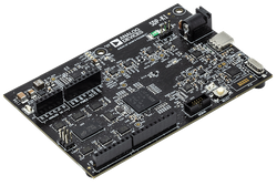
- SDP-K1 overview
- Arduino headers
- 120-pin SDP connector
- High performance ARM® Cortex™-M4 Core (STM32F469NI)
- 180 MHz max CPU frequency, 384 KB SRAM, 2048 KB Flash
- 1.8V or 3.3V selectable IO voltage
- 480Mbps High-Speed USB 2.0 with USB-C connector (Device)
- 45MHz SPI at 3.3V & 22.5MHz at 1.8V
- 400KHz I2C
- UART
- Timers / PWM
- 12-bit ADC
- GPIO
- 16MB SDRAM
- 3 traffic light LEDS (green, orange, red)
- 1 status LED
Board Components


Board Pinout
Arduino Uno Header Pinout

SDP Connector Pinout

The pinout diagrams above shows the commonly used features and their locations.
You can find more details on the available pins and labels in the PinNames.h and PeripheralPins.c files of SDP-K1. The PinNames.h file contains all of the aliased signals that the SDP-K1 can use when writing Mbed code. The PeripheralPins.c contains the peripheral functionality that each pin can access on the SDP-K1 when writing Mbed code.
Using the SDP connector
Note if you use the SDP connector signals on your board it will not be portable between other Mbed controller boards as this is unique to the SDP-K1
The SPI signals for SCK, MISO & MOSI of the SDP connector can be used in Mbed by defining the following signals with the standard SPI definition in Mbed
- SDP_SPI_MOSI
- SDP_SPI_MISO
- SDP_SPI_SCK
On the SDP connector there are 3 different chip selects that can be used, to use these in Mbed they need to be defined as follows
- SDP_SPI_CS_A,
- SDP_SPI_CS_B ,
- SDP_SPI_CS_C
The I2C on the SDP connector, can be enabled using the following definitions
- SDP_I2C_SDA
- SDP_I2C_SCL
The 8 GPIOs on the connector , can be enabled using the following definitions
- SDP_GPIO_0
- SDP_GPIO_1
- SDP_GPIO_2
- SDP_GPIO_3
- SDP_GPIO_4
- SDP_GPIO_5
- SDP_GPIO_6
- SDP_GPIO_7
The UART on the SDP connector, can be enabled using the following definitions
- SDP_UART_TX
- SDP_UART_RX
The Timers on the SDP connector, can be enabled using the following definitions
- SDP_TMR_A
- SDP_TMR_B
- SDP_TMR_D
The QSPI signals for SCK, and the four data lines on the SDP connector can be used in Mbed by defining the following signals with the standard QSPI definition in Mbed
- SDP_QSPI_SCK
- SDP_QSPI_D0
- SDP_QSPI_D1
- SDP_QSPI_D2
- SDP_QSPI_D3
Getting Started with mbed
1. Connect SDP-K1 board to a PC
Use the USB lead to connect your SDP-K1 to a PC. The SYS_PWR LED will come on, indicating the board has power. After a few seconds of activity, the PC will recognize the SDP-K1 as a standard USB drive.

Windows 10 example

Mac OS X example
2. Click the MBED.HTM link to get logged in
Go to the new USB Drive, and click MBED.HTM to open it in a web browser.
If you do not have an mbed account, choose "Signup", and create your mbed Account. Otherwise, log in with your normal username and password.
This will give you access to the website, tools, libraries and documentation.
PC Configuration
Your SDP-K1 Microcontroller can appear on your computer as a serial port. On Mac and Linux, this will happen by default. For Windows, you need to install a driver:
Windows
See Windows-serial-configuration for full details about setting up Windows for serial communication with your mbed Microcontroller
From a host PC to communicate with mbed you will need a terminal application. This allows the mbed Microcontroller to print to your PC screen, and for you to send characters back to your mbed.
- Terminals - Using Terminal applications to communicate between the Host PC and the mbed Micrcontroller
Some terminal programs (e.g. TeraTerm) list the available serial ports by name. However, if you do need to know the identity of the serial port so that you can attach a terminal or an application to it:
| Windows | Mac | Linux | ||||
| Find the identity of the COM port by opening ''Device Manager''. To do this navigate ''Start -> Control Panel -> System -> Hardware -> Device Manager''. | To find the device name under Mac OS X, use the command ''ls /dev/tty.usbmodem*'' | To find the device name under Linux, use the command ''ls /dev/ttyACM*'' | ||||
 |  |  |
Downloading a program
1. Save a program binary (.bin) to the Platform
Download the appropriate "Hello World!" binary:
- SDP-K1: SDP_K1_blinky_program.bin
Note: the source code for this program will be seen in the next section.
Save the program binary file to your mbed Microcontroller Disk, just like you would with a normal USB disk. The Status LED will flash as the PC writes the file to the Microcontroller disk. The file is now consumed.

2. Press the Reset Button
When the Reset Button in pressed, the microcontroller will be reset and the last programmed application will begin to run.
3. Hello World!
The Microcontroller is now running the program; flashing LED4 forever! If you reset the Microcontroller, or disconnect and reconnect the power, the program will simply restart.
Where Next
For further information on getting started and using the online compiler or Mbed studio consult the following documentation
To purchase an SDP-K1 (EVAL-SDP-CK1Z), please visit the Analog store page here.
Technical Reference
Power
- The SDP-K1 can be powered in several different ways
- USB powered at 5V (+/- 10%)
- DC Jack powered at 7V - 12V
- Vin pin on Arduino Uno header is bidirectional and can supply voltages between 7V -12V
- However, this depends on the Arduino Uno shield you are using
- SDP connector Vin pin can supply 5V at 300mA to the SDP-K1
- However, this depends on the ADI evaluation board you are using
- Arduino Uno supplies are as follows
- Vin 7V-12V
- 3.3V
- 5V
- IOREF is a voltage reference for peripherals on the digital I/O pins
- Voltage can be either 1.8V or 3.3V depending on the VIO adjust headers configuration
- The IOREF should not be treated as an actual voltage supply
- SDP Connector
- USB VBUS is a 5V output supply
- SDP Vin is a 5V input supply capable of powering the SDP-K1
- VIO is a voltage reference for the peripherals on the digital I/O pins
- Voltage can be either 1.8V or 3.3V depending on the VIO adjust headers configuration
- The IOREF should not be treated as an actual voltage supply
Schematic
Schematic - SDP-K1 Rev B
Schematic - SDP-K1 Rev E
BOM
BOM - SDP-K1 Rev B
BOM - SDP-K1 Rev E
CMSIS DAPLink Firmware Update
The DAPLink Interface on the SDP-K1 comes with Automation Mode set and the following steps are needed for updating the firmware:
1. Drag and drop an empty file named start_bl.act into the drive. You should see a drive appear in your file manager called MAINTENANCE.

2. Drag and drop this hex file into the drive:
SDP_K1_DAPlink_firmware_image_1.0.5.
You need to log in to post a discussion
To compile a program for this board using Mbed CLI, use SDP_K1 as the target name.
Board Partner
Analog Devices
ADI enables our customers to interpret the world around us by intelligently bridging the physical and digital with unmatched technologies that sense, measure and connect. We collaborate with our customers to accelerate the pace of innovation and create breakthrough solutions that are ahead of what’s possible.
Silicon Partner
ST
A world leader in providing the semiconductor solutions that make a positive contribution to people’s lives, both today and in the future.
 Mbed Enabled
- Baseline
Mbed OS support
- Mbed OS 5.12
- Mbed OS 5.13
- Mbed OS 5.14
- Mbed OS 5.15
- Mbed OS 6.0
- Mbed OS 6.1
- Mbed OS 6.10
- Mbed OS 6.11
- Mbed OS 6.12
- Mbed OS 6.13
- Mbed OS 6.14
- Mbed OS 6.15
- Mbed OS 6.2
- Mbed OS 6.3
- Mbed OS 6.4
- Mbed OS 6.5
- Mbed OS 6.7
- Mbed OS 6.8
- Mbed OS 6.9
Example programs