MultiTech xDot (MAX32670)
The xDot® is a low cost, low power LoRa Module.
Overview
The xDot® is a secure, CE/FCC/RCM/GITEKI certified, Arm® Mbed™ programmable, low-power RF module, that provides long-range, low bit rate M2M data connectivity to sensors, industrial equipment and remote appliances.
The xDot is LoRaWAN® 1.0.4 compliant, providing bi-directional data communication up to 10 miles/15 km line-of-sight and 1-3 miles / 2 km into buildings, using sub-GHz ISM bands in North America, Europe, Australia (AU915), Asia Pacific (AS923), India (IN865) and Korea (KR920).
xDots bring intelligence, reduced complexity and a lower overall bill of material cost to the very edge of the network while supporting a variety of electronic interfaces to connect just about any “Thing” for years on battery power.
Actual performance speeds may be affected by a variety of attributes such as distance from gateway, data loads, packet sizes, etc. Note: AS923 models are for use in many Asia Pacific countries. At this time regulatory approvals are pending. Contact your MultiTech sales representative for more information.
Key Benefits
- Excellent performance in harsh radio environments
- Range of 10 miles/15 km line-of-sight
- Deep in-building penetration - 1 to 3 miles / 2 km
- Developer friendly to integrate and quickly deploy assets
- Runs for years on battery power
Features
- FCC/CE/RCM/GITEKI certified for use in North America, Europe, Australia and Japan
- LoRaWAN CertifiedCM
- Unicast and Multicast message support
- Multiple I/O interfaces for connecting almost any "Thing"
- Data rates 293bps - 20Kbps + LoRa®
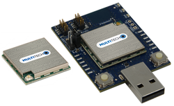
xDots can be purchased as standalone modules for design-in or mounted on the xDot-DK developer board.
Radio Compliance
MultiTech has certified the xDot for compliance with US and Foreign compliance bodies including FCC, R&TTE, and others. (e.g. FCC 15.247:2015 & IC RSS-210:2010)
MultiTech provides software meant to operate the LoRa radio to a level that maintains compliance with the operating modes under which these radio devices were certified. To ensure this level of compliance, the software code is provided in binary form only. Users are prohibited from making any changes that affect the operation of the radio performance. Accessing or controlling the radio through any means other than the provided binary software will require the user to obtain their own intentional radiator license from the certification body governing their locality, as all precertification provided with MTDOT-x will have been made invalid.
xDot Pinout Diagram

Pin limitations
- GPIO are not 5V tolerant
- GPIO are digital only (no analog support)
xDot Features
- MAX32670 Processor
- Powerful ARM® Cortex™-M4 processor
- 100MHz, 160kB SRAM, 384kB Flash
- SPI (1)
- I2C (1)
- UART (2) - 1x 4-pin TX/RX/RTS/CTS, 1x 2-pin TX/RX
- PWM (10 total, 2 low power)
- GPIO (up to 19)
- Sx1262 Radio
- Range of 10 miles/15 km line-of-sight
- Deep in-building penetration - 1 to 3 miles / 2 km
- Receive current of only 4.2ma
- Transmit power up to +22dBm
- 2-way duplex communication, ideal for emergency or mission-critical applications
- LoRaWAN data rates 293bps - 20 Kbps + FSK up to 300Kbps
- Power
- 2.41V to 3.57V external power
- Current (deep sleep): 1.0 uA
- Maximum of 25 mA current source/sink by any GPIO pin
- Maximum of 100 mA current source/sink all GPIO pins combined
- All GPIO pins are 3.3v tolerant
xDot-DK Pinout Diagram
The table on the right maps xDot-DK pin names to xDot pin names where they differ.
| xDot-DK Pin | xDot mbed Pin | Processor pin |
|---|---|---|
| UART1_TX | UART_TX | P0.9 |
| UART1_RX | UART_RX | P0.8 |
| UART1_CTS | UART_CTS | P0.10 |
| UART1_RTS | UART_RTS | P0.11 |
| I2C0_SDA | I2C_SDA | P0.13 |
| I2C0_SCL | I2C_SCL | P0. 12 |


xDot-DK Features
- Debug and Programming Interface Circuit
- [USB MSC] Drag-n-drop programming
- [USB CDC] USB Serial Port
- [USB HID] CMSIS-DAP
- Power
- 5V USB power or 2.41V to 3.57V external power
- Please see the xDot-AD Developer Guide if powering DK from external power
- Power draw measurement isolation via JP30
- 5V USB power or 2.41V to 3.57V external power
- Form factor
- Approximately 2" x 1.5"
- Onboard Sensors
- None
- None
Getting Started with mbed
1. Connect the xDot to your PC
See the "Getting Started" chapter in the xDot-AD developer guide
2. mbed documentation links
For tool chain options see the mbed quick start. Using mbed studio with the ARMC6 compiler is recommended as the quickest way to get started.
Hello World
1. Write a binary program to the xDot
Download the "Hello World!" blinky binary:
Drag and drop the binary file to the xDot microcontroller disk, just like you would with a normal USB disk. The Status LED on the DK board will flash as the xDot is being programmed.
2. Hello World!
The xDot should be executing the blinky program flashing LED1, on the DK board, forever and printing "blink" at 115200bps on the AT command port. If you press the reset button on the DK board, the xDot will reset and print a couple boot loader messages on the debug port at 115200bps.
3. Blinky tutorial
4. Official mbed blinky example source code
Example Programs
The following programs support multiple Dot devices. Before the dot-examples or AT firmware are compiled, a Dot library must be imported. See the Dot-Examples or Dot-AT-Firmware landing pages for more details.
Dot Examples
Click here for dot-examples on github
Import programDot-AT-Firmware
AT command firmware for MultiTech Dot devices.
Last commit 15 Jan 2025 by ![]() MultiTech
MultiTech
The mbed OS API References contain example code which demonstrates how to use common peripherals like Digital IO, Analog IO, Serial, SPI, I2C, PWM, RTOS, Timers, Tickers, etc.
FOTA
To support FOTA on the xDot-AD, an external flash memory is included. The FOTA code in the xDot-AD library writes the firmware to the external flash memory. Our bootloader must be included as it writes the new firmware image to the processor.
The Dot-examples above include a FOTA example. The factory AT command firmware also supports FOTA.
xDot Bootloader
The xDot can include a bootloader to allow applications to be upgraded via FOTA or via serial without the need for a developer board. See this article and this wiki page describing how the bootloader can be used for more information.
A bootloader binary can be specified in the project's mbed_app.json file. See this article, our example programs, and here for details.
Bootloader binaries are available on GitHub.
Factory Firmware
The xDot ships from the factory pre-loaded with our custom AT Command Firmware. This firmware provides a serial AT command interface for configuring and using the xDot. It can be used in production when using a separate host processor that controls the mDot via AT commands and during development for testing LoRa transmissions. It is available here. AT command documentation is available here.
LoRa Stack (libxDotAD)
The Dot library(LoRa Stack) provides a LoRaWan certified stack for LoRa communication. This is for use in any custom LoRaWAN application for the xDot-AD. See the Dot-Examples above for integration examples.
Note
The stable xDotAD library is not available yet and the mbed pages for xDotAD stable and dev have not been setup yet.
Version 4
Dot Library versions 4.x.x are compiled with mbed-os 6. Stable production build is hosted on mbed and GitHub for convenience.
Commit messages specify the version of mbed-os it was compiled against. We recommend building your application with the version of mbed-os specified in the commit message of the version of the Dot library you're using. This will ensure that you don't run into any runtime issues caused by differences in the mbed-os versions.
Supported Toolchains and Versions
Development and production builds of the Dot Library currently only support the ARMC6 and GCC_ARM toolchains. The IAR toolchain is not supported at this time. ARMC6 is suggested for production builds, it also provides reduced firmware size and RAM usage compared with GCC_ARM builds.
Stable Production Build
This build of libxDot is stable, tested, and suitable for deployment scenarios. It is hosted on mbed and GitHub for convenience.
Bleeding Edge Development Build
This build of libxDotAD-dev contains bug fixes and new feature development which may not be complete. It is not guaranteed to be stable or well-tested and is not suitable for deployment scenarios. It is hosted on mbed and GitHub for convenience.
Usage
The Dot Library requires a channel plan to be injected into the LoRa stack. Available channel plans can be found be in the Dot Library repository in the plans folder.
The following code demonstrates the basics for setting up the LoRa stack.
Setting up the mDot instance
#include "mDot.h"
#include "ChannelPlans.h"

int main() {
    // use US915 plan
    lora::ChannelPlan* plan = new lora::ChannelPlan_US915();
    // use EU868 plan
    // lora::ChannelPlan* plan = new lora::ChannelPlan_EU868();
    assert(plan);

    // inject channel plan into LoRa stack
    mDot* dot = mDot::getInstance(plan);
    assert(dot);

    // your code ...

    return 0;
}
Threads
The Dot Library starts two threads. One to manage LoRa radio, MAC, and link layers. Another to manage LoRa application layer for multicast and FOTA. Each of these threads are allocated 2048 bytes for their stacks.
Offline IDE
It is possible to compile for the xDot and debug them on the xDot using the Eclipse IDE. See our wiki page for more information.
Technical Reference
xDot Documentation
Note
Links will be updated to specific PDFs once available
- xDot Quick Start Guide
- xDot Data Sheet
- xDot Developer Guide
- Includes xDot-DK schematics and board files
- MultiTech xDot AT Command Guide
Component Documentation
xDot Dev Kit Interface Firmware
The xDot-DK contains a processor that runs daplink firmware which provides a drag and drop interface for easy programming of the xDot. To update the interface firmware on your xDot-DK, follow these steps:
- Click here to download the daplink firmware for the xDot-DK.
- While holding down the reset button, plug the xDot-DK into your PC. After a drive called MAINTENANCE enumerates, the reset button can be released.
- Drag and drop the new firmware onto the MAINTENANCE drive.
- After the new firmware programs, the XDOT drive should appear. The DETAILS.TXT file should reflect the new DAPLink firmware version.
You need to log in to post a discussion
Silicon Partner
Maxim Integrated
Maxim's microcontrollers provide low-power, efficient, and secure solutions for challenging embedded applications.