MultiTech Dragonfly
The MultiConnect® Dragonfly offers developers an FCC and carrier certified solution that makes connecting sensors and other edge-of-network devices quick and easy.
Information
This page is for the Dragonfly(MTQ)
For the Dragonfly Nano(MTQN) click here
Overview
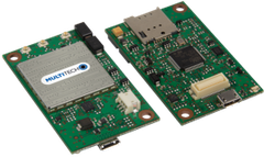
The MultiConnect® Dragonfly™ cellular SoMs are complete, ready-to-integrate processing and communications devices that offer developers the functionality of a SoM with the convenience of an onboard cellular radio all in one compact design. With its integrated Cortex M4 processor, developers can host their application and have access to a full suite of interfaces for connecting sensors or other remote assets.
Dragonfly also comes with an ARM mbed compatible software library for even faster development. This powerful suite of hardware and software products greatly reduces your time to market and makes your Internet of Things (IoT) device a reality today.
Key Benefits
- End device certified by leading carriers
- Family of cellular options include 4G-LTE, 3G HSPA+, 3G EV-DO and 2G 1xRTT
- Developer friendly to integrate, quick to deploy and scale assets
- Long solution lifecycle reduces redesign time and cost
Features
- Lightweight SoM ideal for most IoT applications
- On-board GNSS or GPS for fast and accurate location fix (3G models)
- Arm® Mbed™ OS enabled
- Multiple I/O interfaces for connecting most any “Thing”
- Design in or retrofit
Offline Development Options
It is possible to develop offline for the Dragonfly using mbed-cli and the Eclipse IDE. See our wiki page for more information.
Developer Kit Required
To program and use the Dragonfly, you will need a Developer Kit.
Dragonfly Pinout Diagram

The pinout diagram above shows the commonly used interfaces and their locations. In addition to their stated functions, all GPIO pins (PA_*, PB_*, PC_*) can also be used as DigitalIn and DigitalOut interfaces.
InterruptIn Limitations
Due to the processor's architecture, only one pin of the same number (e.g. PA_1 & PB_1) may be configured as an InterruptIn. If multiple pins of the same number are configured as InterruptIn, only the last pin configured will actually trigger an interrupt in the processor. The rest will be ignored.
PwmOut Limitations
PwmOut objects using different channels of the same timer must use the same prescaler value. Each timer has a single prescaler which applies to all channels in the timer.
For STM32F411 devices, two possible prescaler values are allowed:
- 1us which allows for a period/pulse from 1us to 65535us
- 500us which allows for a period/pulse from 500us to 32.76s
5V Tolerant IO Limitations
If the external voltage on a GPIO is greater than VDD + 0.3V, use of the internal pullup or pulldown resistors could damage the Dragonfly. External pullup or pulldown resistors should be used instead.
For more information see the notes below section 6.3.1 of the STM32F411RE Data Sheet.
Dragonfly Features
- STM32F411RET Processor
- High performance ARM® Cortex™-M4 Core
- 96MHz, 128kB RAM, 512kB Flash
- SPI (2)
- I2C (2)
- UART (2) - 1x 8-pin TX/RX/RTS/CTS/DCD/DTR/DSR/RI, 1x 2-pin TX/RX
- PWM (15)
- ADC (12 bit ADC with 12 channels)
- GPIO (up to 31)
- Telit Cellular Radio
- Connected to Processor via UART
- TCP & UDP Sockets
- SMS Messaging
- GPS Location (on some radios)
- Power
- 3.3V to 5V external power
- Current (active): Refer to product device guide
- Current (sleep): 6mA (radio off)
- Maximum of 25 mA output current sourced by any IO pin
- Maximum of 120 mA output current sourced by sum of all IO pins
- All IO pins are 3.3v tolerant
- 29 5V tolerant IO pins (see Dragonfly Pinout Diagram)
- Internal pullup and pulldown resistors cannot be used on 5V tolerant GPIO pins when pin voltage is greater than VDD + 0.3V. See warning box above
Cellular Stack (MTSCellularInterface)
Information
This code is for the Dragonfly(MTQ) not the Dragonfly Nano(MTQN). It has been tested and developed against mbed-os version 5.4.7. Later versions of mbed-os may not be compatible.
The MTSCellularInterface library implements the mbed-os CellularInterface for the cellular radios on MultiTech Dragonfly devices. MTSCellularInterface provides TCP and UDP sockets, SMS messaging capabilities, and GPS location*. After cloning this repository, run the setup script (setup.sh or setup.bat) to generate the version header and clone required dependencies. The library can be cloned from GitHub.
* Not all radios support GPS. GPS location requires a lock on GPS satellites, which may not be possible indoors.
Example Programs
Import our example programs to get up and running quickly and easily, then modify them to create your own solution using the Dragonfly!
Most radios require an APN string to be set before the radio can be used. The APN can be set in the source of the specific example you're using. The SMS example also needs a phone number to send/receive SMS messages to/from.
Import programDragonfly-Examples
Example programs for MultiTech Dragonfly devices demonstrating how to use the MultiTech MTSCellularInterface library for cellular radio communication and control.
Last commit 21 May 2018 by ![]() MultiTech
MultiTech
Old Cellular Stack (MTSAS)
This old cellular stack is not compatible with mbed-os. Consider using MTSCellularInterface instead!
Import librarymtsas
Complete library supporting MultiConnect Dragonfly and SocketModem Arduino Shield devices.
Last commit 09 Sep 2015 by ![]() MultiTech
MultiTech
Old Example Programs
These old example programs use the deprecated MTSAS library which is not compatible with mbed-os. Consider using Dragonfly-Examples and MTSCellularInterface instead!
Import programDragonfly_Cellular_Ping_Example
Ping a server using the onboard cellular radio.
Last commit 26 Feb 2016 by ![]() MultiTech
MultiTech
Import programDragonfly_Cellular_SMS_Example
Send and receive SMS messages using the onboard cellular radio.
Last commit 26 Feb 2016 by ![]() MultiTech
MultiTech
Import programDragonfly_Cellular_HTTP_Example
Does HTTP GET and POST requests using the onboard cellular radio.
Last commit 26 Feb 2016 by ![]() MultiTech
MultiTech
Import programDragonfly_Cellular_HTTPS_Example
Does HTTPS GET and POST requests using the onboard cellular radio.
Last commit 26 Feb 2016 by ![]() MultiTech
MultiTech
Factory Firmware
The Dragonfly ships from the factory pre-loaded with AT Passthrough Firmware. This firmware implements serial passthrough and provides direct access to the cellular radio via the external serial port on the MTUDK2. It is available here.
Offline IDE
It is possible to compile for the Dragonfly and debug them on the Dragonfly using the Eclipse IDE. See our wiki page for more information.
MTS Bootloader
Information
After mbed-os-6.1.0, the bootloader is no longer automatically added to the application for the Dragonfly. However our bootloader still resides in mbed and can be added to the application. To add our bootloader, you need to include an mbed_app.json file that defines where the bootloader can be found.
"target_overrides": {
    ...
    "<TARGET_NAME>": {
        "target.bootloader_img": "mbed-os/tools/bootloaders/MTS_DRAGONFLY_F411RE/bootloader.bin"
    },
    ...
You can also point elsewhere to include some other bootloader
The Dragonfly includes a bootloader which allows applications to be upgraded OTA (Over The Air) or via serial without the need for a developer board. See the wiki page describing how the bootloader can be used for more information.
Technical Reference
Developer kit
Documentation
- Dragonfly Datasheet
- Dragonfly Developer Page
- Dragonfly device guides and AT command guides are specific to the radio type and can be found here.
Data Sheets
Interface Firmware
The MTUDK2 uses the same ST-Link interface firmware as many of the ST Nucleo boards. The latest interface firmware and instructions for upgrading can be found here.
Getting Started with mbed
1. Connect your microcontroller to a PC
Use the USB lead to connect your mbed to a PC. The status light will come on, indicating it has power. After a few seconds of activity, the PC will recognise the mbed Microcontroller as a standard USB drive.
 |  |
| Windows XP example | Mac OS X example |
2. Click the MBED.HTM link to get logged in
Go to the new USB Drive, and click MBED.HTM to open it in a web browser.
If you do not have an mbed account, choose "Signup", and create your mbed Account. Otherwise, log in with your normal username and password.
This will give you access to the website, tools, libraries and documentation.
PC Configuration
Your mbed Microcontroller can appear on your computer as a serial port. On Mac and Linux, this will happen by default. For Windows, you need to install a driver:
Serial Driver for Debug Port on Windows
The DK boards for the Dragonfly require the ST-Link driver to be installed before the debug serial port can be used on Windows PCs. This driver is different from the mbed Windows serial driver.
From a host PC to communicate with mbed you will need a terminal application. This allows the mbed Microcontroller to print to your PC screen, and for you to send characters back to your mbed.
- Terminals - Using Terminal applications to communicate between the Host PC and the mbed Micrcontroller
Some terminal programs (e.g. TeraTerm) list the available serial ports by name. However, if you do need to know the identity of the serial port so that you can attach a terminal or an application to it:
| Windows | Mac | Linux | ||||
| Find the identity of the COM port by opening ''Device Manager''. To do this navigate ''Start -> Control Panel -> System -> Hardware -> Device Manager''. | To find the device name under Mac OS X, use the command ''ls /dev/tty.usbmodem*'' | To find the device name under Linux, use the command ''ls /dev/ttyACM*'' | ||||
 |  |  |
On both Mac and Linux PCs, the port with the higher number will be the USB serial debug port. For example, if you have Linux and get ports /dev/ttyACM0 and /dev/ttyACM1, ttyACM1 will be the debug port and ttyACM0 the AT command/secondary port.
Downloading A program
1. Save a program binary (.bin) to the Platform
Download the appropriate "Hello World!" binary:
- MTS_DRAGONFLY_F411RE: mbed-os-example-blinky_mts_dragonfly_f411re.bin
Note: the source code for this program will be seen in the next section.
Save the program binary file to your mbed Microcontroller Disk, just like you would with a normal USB disk. The Status LED will flash as the PC writes the file to the Microcontroller disk. The file is now consumed.
2. Press the Reset Button
When the Reset Button in pressed, the microcontroller will be reset and the last programmed application will begin to run.
3. Hello World!
The Microcontroller is now running the program; flashing LED1 forever! If you reset the Microcontroller, or disconnect and reconnect the power, the program will simply restart.
Hello World!
[Repository '/teams/mbed-os-examples/code/mbed-os-example-blinky/' not found]
In its current state, the program will blink the D3 LED on a MTUDK2 board.
Where Next
Follow the guide to creating your own programs using the online compiler
You need to log in to post a discussion
Questions
 miao zhicheng
 6 years, 11 months ago
 Hasnain Virk
 7 years, 4 months ago

To compile a program for this board using Mbed CLI, use MTS_DRAGONFLY_F411RE as the target name.
Silicon Partner
ST
A world leader in providing the semiconductor solutions that make a positive contribution to people’s lives, both today and in the future.
 Mbed Enabled
- Baseline
Mbed OS support
- Mbed OS 2
- Mbed OS 5.4
- Mbed OS 5.5
- Mbed OS 5.6
- Mbed OS 6.0
- Mbed OS 6.1
- Mbed OS 6.10
- Mbed OS 6.11
- Mbed OS 6.12
- Mbed OS 6.13
- Mbed OS 6.14
- Mbed OS 6.15
- Mbed OS 6.2
- Mbed OS 6.3
- Mbed OS 6.4
- Mbed OS 6.5
- Mbed OS 6.6
- Mbed OS 6.7
- Mbed OS 6.8
- Mbed OS 6.9
Example programs