MAX32630FTHR
MAX32630 Rapid Development Platform
Overview
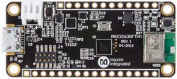
The MAX32630FTHR board is a rapid development platform designed to help engineers quickly implement battery optimized solutions with the MAX32630 ARM Cortex-M4F microcontroller. The board also includes the MAX14690N Wearable PMIC to provide optimal power conversion and battery management. The form factor is a small 0.9” by 2.0” dual row header footprint that is compatible with breadboards and off-the-shelf peripheral expansion boards. Additionally, onboard are a variety of peripherals including a dual mode Bluetooth module, micro SD card connector, 6-axis accelerometer/gyro, RGB indicator LED, and pushbutton. This provides a power-optimized flexible platform for quick proof-of-concepts and early software development to enhance time to market.
This pinout and form-factor for this board are based on the Adafruit feather series of boards and it is intended to be compatible with many of their peripheral wings, but it is not guaranteed to work with all FeatherWings.
A MAX32630FTHR APPS wiki page is available with more hints and examples.
Pinout
 The pinout diagram above shows the commonly used interfaces and their locations. Note that all the numbered pins (Pn_n) can also be used as DigitalIn, DigitalOut, DigitalInOut and PwmOut interfaces.
Peripheral Interfaces


Features
- MAX32630 Ultra-Low Power Microcontroller
- High performance ARM® Cortex™-M4F Core
- 96MHz, 512KB SRAM, 2048KB Flash
- Ultra-Low Power for Battery Applications
- 106µA/MHz Active Executing from Flash
- 600nA Low Power Mode with RTC Enabled
- 3.5µW Ultra-Low Power Data Retention Mode
- 5µs Fast Wakeup to 96MHz
- Peripherals
- USB 2.0 Full-Speed Device
- SPI, I2C, UART, 1-Wire Serial Interfaces
- RTC, PWM, AES
- Four-Input 10-Bit ADC
- 66 Dual Voltage GPIO
- Tiny 100-Ball 4.37mm X 4.37mm WLP
- MAX14690 Wearable PMIC
- Battery Charger with Smart Selector
- Dual Micro Iq Buck Regulators
- Three Micro Iq Linear Regulators
- Power On/Off Sequencing Controller
- Voltage Monitor Multiplexer
- Expansion Connections
- Breadboard compatible headers
- Micro SD Card Connector
- JST Battery Connector
- Micro USB Connector
- Integrated Peripherals
- RGB Indicator LED
- 6-axis Accelerometer/Gyro
- Dual-mode Bluetooth module
- User push-button
- Remote mbed HDK Debug Interface (included with purchase of MAX32630FTHR)
- [USB MSC] Drag-and-drop programming
- [USB HID] SWD Debugger
- [USB CDC] Virtual UART Console
Firmware
MAXREFDES100HDK Firmware Update
The MAX32630FTHR board ships with an external DAPLink adapter such as the MAXREFDES100HDK. Please visit our MAXREFDES100HDK wiki page for details on how to load the correct firmware onto your adapter.
Getting Started with MAX32630FTHR
1. Connect the MAX32630FTHR to the MAXREFDES100HDK
Use the fine pitch 10-pin ribbon cable to connect the boards from the SWD (J3) header on the HDK to J4 on the MAX32630FTHR.
2. Connect the MAX32630FTHR to a power source
Use a micro USB cable to connect the MAX32630FTHR board to a suitable power source (no USB connectivity is required). Alternatively, you can power the board from a charged battery as long as you remember to turn it on by pressing the power/reset button next to the battery connector. The board turns on automatically when powered from the USB supply.
3. Connect the MAXREFDES100HDK to a PC
Use a micro USB cable to connect the HDK to a PC, through the connector marked HDK. The status light will come on, indicating it has power. After a few seconds of activity, the PC will recognize the mbed Microcontroller as a standard USB drive.
 |  |
| Windows XP example | Mac OS X example |
4. Click the MBED.HTM link to get logged in
Go to the new USB Drive, and click MBED.HTM to open it in a web browser. This will take you to the MAX32630FTHR platform page. If you end up at a different page, go to our MAXREFDES100HDK wiki page for details on how to load the latest firmware.
If you do not have a mbed account, choose "Signup", and create your mbed Account. Otherwise, login with your mbed username and password.
This will give you access to the website, tools, libraries, and documentation.
PC Configuration
Your mbed Microcontroller can appear on your computer as a serial port. On Mac and Linux, this will happen by default. For Windows, you need to install a driver:
Windows
See Windows-serial-configuration for full details about setting up Windows for serial communication with your mbed Microcontroller
From a host PC to communicate with mbed, you will need a terminal application. This allows the mbed Microcontroller to print to your PC screen, and for you to send characters back to your mbed.
- Terminals - Using Terminal applications to communicate between the Host PC and the mbed Microcontroller
Some terminal programs (e.g. TeraTerm) list the available serial ports by name. However, if you do need to know the identity of the serial port so that you can attach a terminal or an application to it:
| Windows | Mac | Linux | ||||
| Find the identity of the COM port by opening ''Device Manager''. To do this navigate ''Start -> Control Panel -> System -> Hardware -> Device Manager''. | To find the device name under Mac OS X, use the command ''ls /dev/tty.usbmodem*'' | To find the device name under Linux, use the command ''ls /dev/ttyACM*'' | ||||
 |  |  |
Downloading A program
1. Save a program binary (.bin) to the Platform
Download the appropriate "Blinky" binary:
- MAX32630FTHR: blinky_max32630fthr.bin
Note: the source code for this program will be seen in the next section.
Save the program binary file to your mbed Microcontroller Disk, just like you would with a normal USB disk. The Status LED will flash as the PC writes the file to the Microcontroller disk. The file is now consumed.
2. Press the Reset Button
When the Reset Button is pressed, the microcontroller will be reset and the last programmed application will begin to run.
3. Blinky
The Microcontroller is now running the program; flashing LED1 forever! If you reset the Microcontroller, or disconnect and reconnect the power, the program will simply restart.
Example Programs
[Repository '/teams/mbed-os-examples/code/mbed-os-example-blinky/' not found]
Import programFTHR_USB_serial
USB serial demo passes data from virtual serial port to debug serial port
Last commit 27 Sep 2019 by ![]() Maxim Integrated
Maxim Integrated
Import programFTHR_SD_Demo
Example program demonstrates SD card library
Last commit 17 Nov 2017 by ![]() Maxim Integrated
Maxim Integrated
Import programFTHR_USBMSD_Demo
USB Mass Storage Device demo with SD card
Last commit 24 Feb 2018 by ![]() Maxim Integrated
Maxim Integrated
Import programMAX32630FTHR_IMU_Hello_World
Simple demo of BMI160 Library
Last commit 17 Nov 2017 by ![]() Maxim Integrated
Maxim Integrated
Import programFTHR_OLED
Adafruit FeatherOLED example for the MAX32630FTHR board
Last commit 08 Feb 2017 by  Greg Steiert
Import programmbed-os-example-ble-HeartRate
This application transmits a heart rate value using the Bluetooth SIG Heart Rate Profile. The heart rate value is provided by the application itself, not by a sensor, so that you don't have to get a sensor just to run the example. The canonical source for this example lives at https://github.com/ARMmbed/mbed-os-example-ble/tree/master/BLE_HeartRate
Last commit 19 Sep 2019 by  mbed-os-examples
BLE Support in mbed OS
Make sure you are using mbed OS 5.5.5 or later for BLE support on the MAX32630FTHR platform.
Where Next
Follow the guide to creating your own programs using the online compiler
A MAX32630FTHR APPS wiki page is also available with more hints and examples.
Technical Reference
Power
- USB or Battery Powered
- 5.0v from USB available on VBUS (when USB is connected)
- SYS supply automatically switches between battery voltage and VBUS when available
- 1.8V regulated output
- Programmable LDO (typically 3.3V)
- Digital IO pins are individually programmable to 1.8V or 3.3V
Power/Reset Button
The button located next to the battery connector acts as both a reset button and power button. When the board is on, pressing the button will drive reset signal going to the MAX32630 and the header pin low.
The board will turn on automatically any time power is applied to the micro USB connector. If an only a battery is connected, you can turn on the board by a half second press to the power/reset button. When the board is on, a 12-second long press will turn the board off. If the long press is applied when operating from battery power, the board will remain off. If USB power is available during the long press, the board will turn off for 1 second and then turn back on.
Note that the header pin labeled PWR is connected in parallel with the power/reset button and pulling this header pin to ground will have the same effect as pressing the button. The header pin labeled RST is the reset signal. Pulling RST to ground will reset the MAX32630, but it cannot turn the board on or off.
Battery Charger
The MAX14690 includes a battery charger suitable for Lithium Ion and Lithium Polymer batteries. The charge current is set by a resistor attached to the SET pin on the MAX14690. The 20K Ohm resistor installed by default sets the charge current at 100mA which is tolerable for most typical batteries with a capacity greater than or equal to 100mAhr. The default charge voltage is 4.2V, but this is programmable by I2C. Please consult the MAX14690 datasheet and the datasheet for your battery to ensure compatibility.
Product Pages
You need to log in to post a discussion
Questions
Danny Jade Perreault 7 years, 8 months ago
Danny Jade Perreault 7 years, 8 months ago
To compile a program for this board using Mbed CLI, use max32630fthr as the target name.
Board Partner
Maxim Integrated
Maxim's microcontrollers provide low-power, efficient, and secure solutions for challenging embedded applications.
 Mbed Enabled
- Baseline
Mbed OS support
- Mbed OS 5.10
- Mbed OS 5.11
- Mbed OS 5.12
- Mbed OS 5.13
- Mbed OS 5.14
- Mbed OS 5.15
- Mbed OS 5.5
- Mbed OS 5.6
- Mbed OS 5.7
- Mbed OS 5.8
- Mbed OS 5.9
- Mbed OS 6.10
- Mbed OS 6.11
- Mbed OS 6.12
- Mbed OS 6.13
- Mbed OS 6.14
- Mbed OS 6.15
- Mbed OS 6.6
- Mbed OS 6.7
- Mbed OS 6.8
- Mbed OS 6.9
Example programs