Test CAN BUS with 2 nodes (transceivers), can't read the sent message

07 Jan 2013

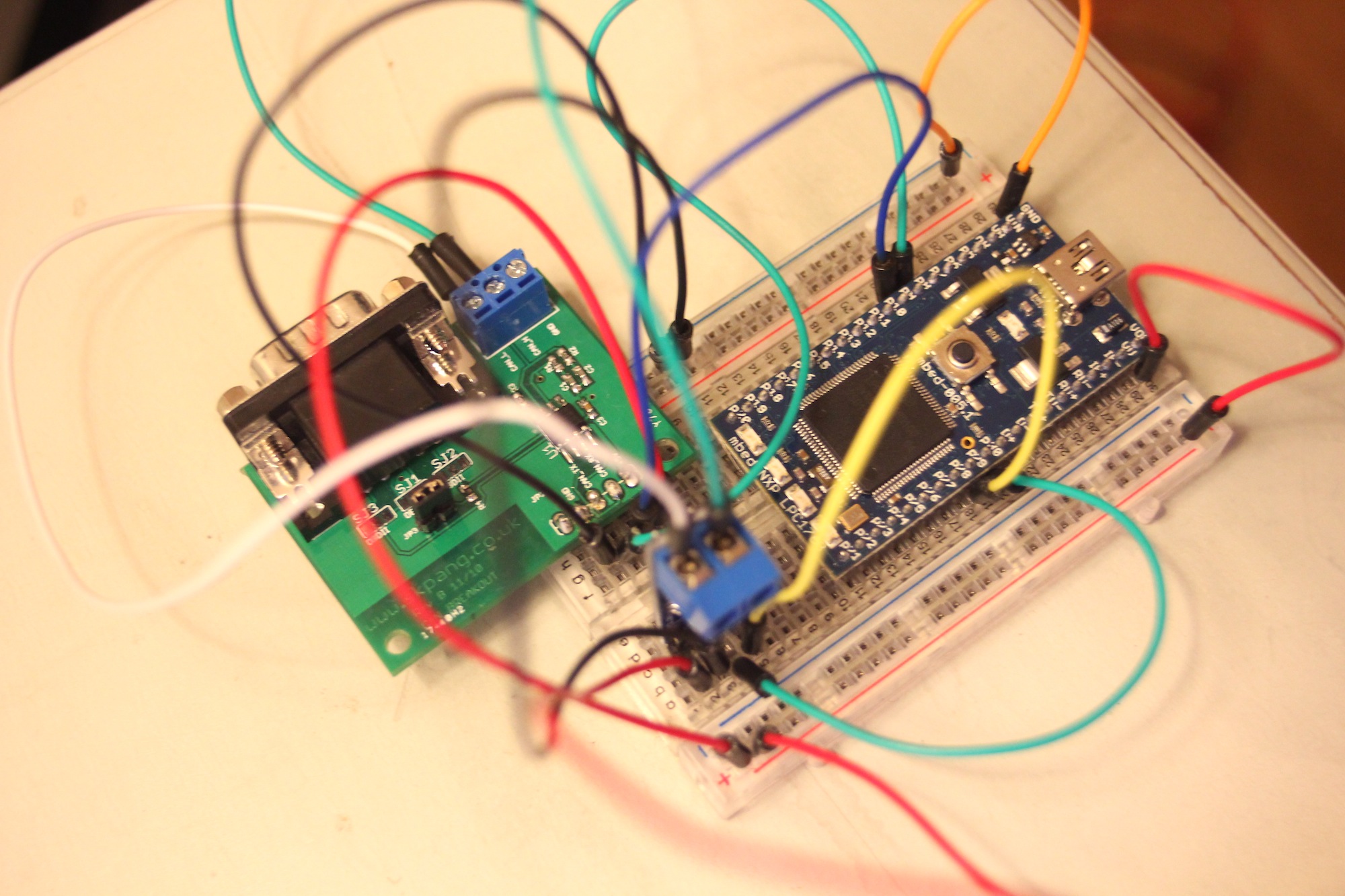
I am using mbed with two different CAN transceivers:

  1. MCP2551 (CAN-Bus Breakout Board from http://www.skpang.co.uk/catalog/canbus-breakout-board-p-754.html)
  2. SN65HVD230 (SN65HVD230 CAN Board from http://www.wvshare.com/product/SN65HVD230-CAN-Board.htm)

(Schematics are in the footer of this post)

with the following wiring:

/media/uploads/kaspars/_scaled_2-can-wiring.jpg

http://mbed.org/media/uploads/kaspars/2-can-wiring.jpg

and from another view:

/media/uploads/kaspars/_scaled_wiring-top.jpg

http://mbed.org/media/uploads/kaspars/wiring-top.jpg

I am running the CAN loopback example provided in the Handbook: http://mbed.org/handbook/CAN but it never receives the message. I also tried to modify the code in order to see rderror() and tderror() for both can1 and can2 and got the following reading via USB serial:

Message sent: 1
CAN1 rderror: 0, tderror: 127
CAN2 rderror: 0, tderror: 0
Message sent: 2
CAN1 rderror: 0, tderror: 176
CAN2 rderror: 0, tderror: 0
Message sent: 3
CAN1 rderror: 0, tderror: 176
CAN2 rderror: 0, tderror: 0
Message sent: 4
CAN1 rderror: 0, tderror: 176
CAN2 rderror: 0, tderror: 0
Message sent: 5
CAN1 rderror: 0, tderror: 176
CAN2 rderror: 0, tderror: 0
Message sent: 6
CAN1 rderror: 0, tderror: 176
CAN2 rderror: 0, tderror: 0
Message sent: 7
CAN1 rderror: 0, tderror: 176
CAN2 rderror: 0, tderror: 0

with the following code:

Import programCAN-node-loop

Testing CAN network with two nodes in loopback

Questions

What do the tderrors mean?

Things I have already tried

  1. Jumpers for 120R on both boards are connected.
  2. Rename can1 to can2 and can2 to can1 and still get the same tderrors.

/media/uploads/kaspars/mcp2551-skpang-can-module.png /media/uploads/kaspars/sn65hvd230-can-module.png

07 Jan 2013

I think you have CAN_RX and CAN_TX of both drivers connected to the wrong pins on mbed.

CAN_RX should go to p9 (CAN_RD1) or p30 (CAN_RD2)

CAN_TX should go to p10 (CAN_TD1) or p29 (CAN_TD2)

This is always a bit confusing since you are are used to connect TXD to RXD and vice-versa for RS232 etc

Also seems you use both 3v3 and 5V powersupply. Probably better to use 3v3 for both drivers.

(Deja vu question! See:

https://mbed.org/forum/helloworld/topic/3014/?page=1#comment-15282)

07 Jan 2013

Thanks for taking a look at this, Wim! I really appreciate it.

Wim Huiskamp wrote:

I think you have CAN_RX and CAN_TX of both drivers connected to the wrong pins on mbed.

I indeed had them connected just like for RS232. I connected them the way you suggested and I still get the same tderror and no reading of messages sent.

Wim Huiskamp wrote:

Also seems you use both 3v3 and 5V powersupply. Probably better to use 3v3 for both drivers.

I connected them both to 3.3V and that didn't help either.

07 Jan 2013

Ok, the problem is that the SK Pang board doesnt adhere to the standard and renamed its pins:

CAN_TX pin on SK Pang is in fact the CAN_RD pin of the driver and

CAN_RX pin on SK Pang is in fact the CAN_TD pin of the driver

So you need to swap the wires back for the SK Pang board breakout board.

07 Jan 2013

Wim Huiskamp wrote:

CAN_TX pin on SK Pang is in fact the CAN_RD pin of the driver and

CAN_RX pin on SK Pang is in fact the CAN_TD pin of the driver

Yes, I noticed that as well when comparing the actual PCB with the datasheet. So my wiring looks like this now:

can1:

  • CAN_RXD (MCP2551) to p9 (CAN_RD1 on mbed)
  • CAN_TXD (MCP2551) to p10 (CAN_TD1 on mbed)

can2:

  • CAN_RXD (SN65HVD230) to p30 (CAN_RD2 on mbed)
  • CAN_TXD (SN65HVD230) to p29 (CAN_TD2 on mbed)

Yet, it still doesn't work and I get the same tderror on the sending controller. The only change is that the error constantly stays at 127. What is the meaning of that value and why doesn't it increase after every failed message?

07 Jan 2013

For the sake of testing I rewired it and put it on a single protoboard, and it still doesn't work.

/media/uploads/kaspars/_scaled_can-bus-wiring-loopback-single-board.jpg

http://mbed.org/media/uploads/kaspars/can-bus-wiring-loopback-single-board.jpg

08 Jan 2013

Your wiring seems to be ok now. I tried out the CAN software on my lpc1768 landtiger board with two onboard SN65HVD230 drivers (see http://mbed.org/users/wim/notebook/landtiger-baseboard/) Communication works as expected. The rderror and tderror are all 0 as long as the CAN network is connected. Values for tderror become somewhat random when I disconnect one of the CAN wires. They seem to slowly countdown and recover when reconnected.

With that result I recommend that you check the wiring for electrical connection. Maybe you have some bad contacts. Try to check directly between mbed pin and contact on the breakout board. Remove power from mbed before conductivity test. You may also try to measure and check the voltages on the CAN bus H/L and check powersupply voltage for the drivers. You should be able to observe the CAN H/L toggling when you connect TD to gnd or 3V3. Remove mbed pins from driverpins before trying that.

You could also try a direct connection between the mbed pins without using the CAN drivers:

p9 (CAN_RD1 on mbed) to p29 (CAN_TD2 on mbed)

p10 (CAN_TD1 on mbed)to p30 (CAN_RD2 on mbed)

That way you can test the comms and mbed pins. Notice that wires are crossed now.

Lets hope it is wiring and you have not fried mbed or one of the drivers.

08 Jan 2013

Thanks for the suggestions, Wim! I really appreciate you time and detailed explanations and suggestions!

I have started reading the LPC17xx CMSIS library source files (which I assume mbed uses) in order to better understand the lower level access that I could use in order to debug this in more detail. I have also ordered two new MCP2551 transceivers just to have something more to play with. I'll post here as soon as I learn something new.

14 Jan 2013

Good news, Wim - I just got two new standalone MCP2551 and everything works perfectly. I shall now find out which was the faulty transceiver of the ones I was trying out in the example above. I am particularly happy to learn that all the experiments that I did have not fried my embed.

12 Dec 2016

Kaspars D wrote:

Good news, Wim - I just got two new standalone MCP2551 and everything works perfectly. I shall now find out which was the faulty transceiver of the ones I was trying out in the example above. I am particularly happy to learn that all the experiments that I did have not fried my embed.

Hi Kaspars D, Can you please show (hardware connections) how you connected two MCP2551 to communicate with each other.Even I am trying to do something similar but am unable to do it. Would be grateful for your help.

Thank you in advance.

Regards Chintu

12 Dec 2016

hi chintu, Here's a Can Tutorial page that may be helpful. It has a simple schematic, using a pair of MCP2551s, and small samples of code.

14 Dec 2016

David Smart wrote:

hi chintu, Here's a Can Tutorial page that may be helpful. It has a simple schematic, using a pair of MCP2551s, and small samples of code.

Hello David, Thank you for your reply.The link you provided is very informative and useful. But I have a question.

Can we connect two MCP2551 directly with each other without any controller (i.e. LPC1768) in between? what i mean is /media/uploads/chintubaba/can_.png

I tried but it didnt work for me. Any suggestions/corrections to this would be helpful.

really grateful for your help Thank you in advance.

Regards Chintu

17 Dec 2016

Hi Chintu,

That's an interesting question, and I don't have an answer for that, except I would suspect it "might work" - depending on a few factors.

In just thinking out-loud about this scenario.

  • In a functional CAN bus, there must be 2 or more nodes. At least one of the receiving nodes must provide a hardware acknowledge to the transmitter. You don't indicate how many nodes might be on the network on the right, but "as shown", that node is listen only, so can't provide the hardware acknowledge.
  • The Tx line in the transceiver on the right should be tied high, to avoid that a floating signal causes transmit errors.

If you intended bi-directional communications:

  • For it to have a better chance of working, the reverse path of Rx to Tx would need to be in place because of that requirement to propagate a hardware acknowledge. (your diagram suggests 1-way communications from right to left).
  • The arbitration and HW ack have somewhat strict requirements and behavior. At very low bit-rates, the extra propagation delays might not be a factor.

I wonder why you would want to do this. If it were to extend the length of the bus, I think you will run into propagation delays that ultimately don't meet the requirements of CAN. This could be a function of the bit-rate you select.

29 Dec 2016

Hello Chintu,
Yes, you can connect CAN transceivers one to another and build a simple CAN repeater. I use them for home automation to build star topology CAN network. But I fully agree with David that using repeaters (similar to using long CAN bus lines) will require to adequately lower the CAN bus speed. This repeater works up to 500kbps. It could be used for connecting two buses as indicated below.

/media/uploads/hudakz/can_repeater_04.png

I have started reading LPC17xx CMSIS library source files. (Which I assume the mbed) to understand access to the lower level where I can use to solve this issue in more detail, the better. I also ordered two new MCP2551 transceiver is just something more to play with. I will post here as soon as I learned new things.

20 Nov 2018

Wim Huiskamp wrote:

You could also try a direct connection between the mbed pins without using the CAN drivers:

p9 (CAN_RD1 on mbed) to p29 (CAN_TD2 on mbed)

p10 (CAN_TD1 on mbed)to p30 (CAN_RD2 on mbed)

That way you can test the comms and mbed pins. Notice that wires are crossed now.

Has anyone tried the direct connection between mbed can pins , as Wim says earlier ?

It doesn't work on my mbed and want to check if my mbed is fried ( I have no tranceivers for testing right now ) !

24 Nov 2018

I haven't tried it yet but according to Siemens application note AP2921 On-Board Communication via CAN without Transceivers all Tx output lines shall be connected to a single data line via fast diodes to avoid short circuits at the output pins.

Warning

Make sure you use +3.3V rather than +5V as pull up voltage with MBED boards!
It is also very important that the current at one port pin does not exceed 1.6 mA.

/media/uploads/hudakz/can_no_transmitters.png